6
Electric/Hydraulic TT Thruster 140 - 300
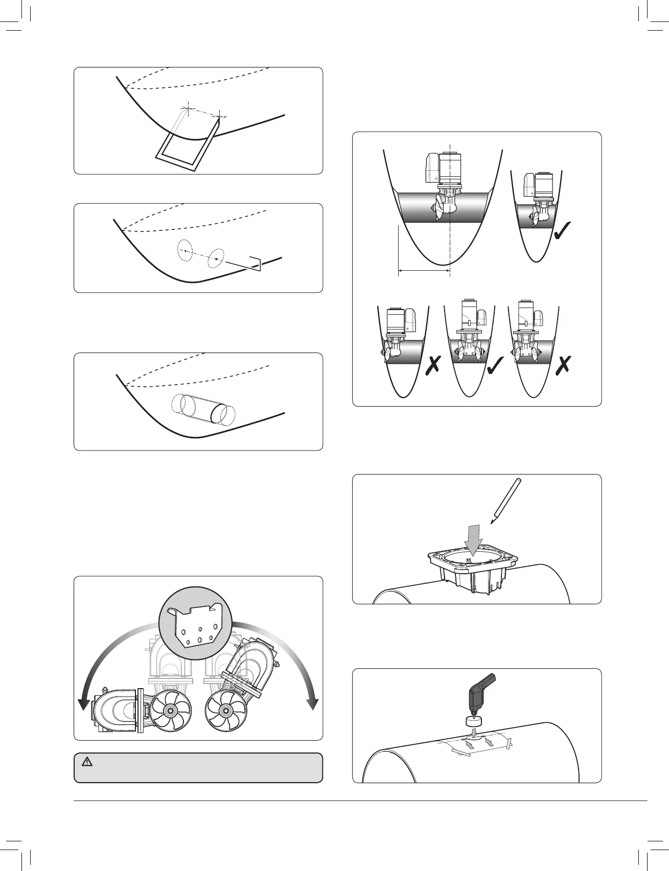
Fig. 1.2.1
Fig. 1.2.2
• Form a wire guide to diameter of the tunnel hole, mark, check
and cut.
• Insert tube in the hole, mark and remove excess.
• Grind off gel coat etc. Insert tunnel and fi x allowing enough
room inside for saddle location on the tunnel.
Gel coat fi nished installation and antifoul.
Fig. 1.2.3
• Drill a pilot hole in both sides of the hull.
1.3 Preparing for fi tting the thruster
• The Thruster can be installed at any angle within 90° from
vertical.
Fig. 1.3.1
Fig. 1.3.2
Fig. 1.3.3
• Choose position of thruster, ensuring internal room for motor
and controls and that the propeller is easily reached from
outside.
NOTE: Fig 1.3.2. - Normal install is
to Port (single propeller unit)
• Position template on centre line, double check everything and
drill. Remove all burrs. All the holes must be on the centre
line. Poor alignment may affect hub positioning.
Fig. 1.3.4
• Place the thruster saddle in the desired position, ensure the
fi t is fi rm and free from movement then mark centre.
• To aid installation a kit is available. See Sec 6.6 Accessories.
Electric motors must be supported if installed more than 30° from
vertical (Fig 1.8.1).
0/04/2007


 To Next Page