Hardware & Software Upgrade Instructions Lexicon
1-4
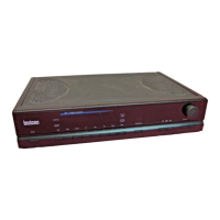
8. Place the unit so it is facing you as shown in Figure 1-3.
Figure 1-3: Front of unit showing main board connector J37.
9. Remove the 3x6mm screw (located behind J37) on the main
board. (Figure 1-4). Put the screw aside for later use.
Figure 1-4: Removing the 3x6mm screw for future use.
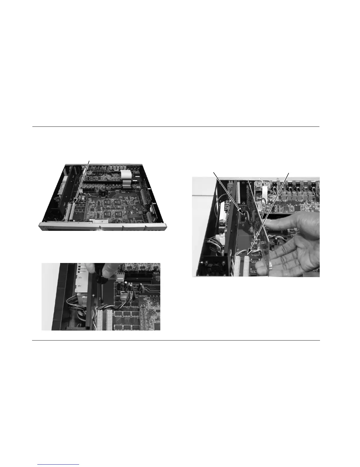
10. Prepare to connect the ribbon cable into connector J19 by
moving the rear of the Microphone Board into position near
connector J19 as shown in Figure 1-5.
Figure 1-5: Board position in preparation for installation.
Connector J37
Connector J19 Connector J37

 Loading...