MC-8 Hardware & Software Upgrade Instructions
1-5
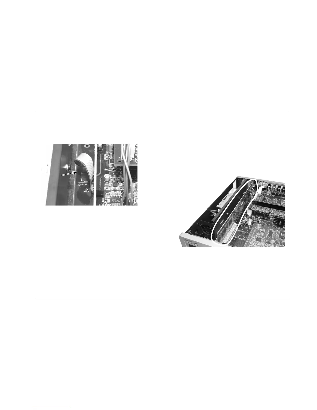
11. Insert the Microphone Board ribbon cable into J19 as shown in
Figure 1-6.
Figure 1-6: Ribbon cable properly inserted into J19.
12. Refer to Figure 1-5. Route the power cables on the main board
so that they run under the notch on the Microphone Board.
13. Slide the back of the Microphone Board under the back edge of
the MC-8 case and position it directly over connector J37.
14. Push the ribbon cable and wires at the front of the unit against
the inside front panel so the board clears them.
15. Carefully insert the Microphone Board into connector J37. The
connector is keyed so the board should insert easily. Do not use
excessive force to make the board fit.
16. Check all cables to ensure that none are pinched or damaged.
Figure 1-7: Properly installed Microphone Board.
J19

 Loading...