1-10
Getting Started
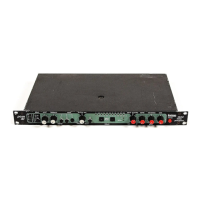
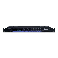
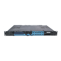
Lexicon
CONTROL CONNECTIONS (continued)
MIDI
Five-pin DIN connectors are provided for MIDI IN, THRU and OUT.
Use standard 5-pin DIN MIDI cable assemblies, available from your
local dealer.
CONNECTORS
Mating
Signal Connector Description
L and R Analog XLR A3M Active balanced, pin 2 high
Audio Input +2dBu min; +20dBu max
at 0dB setting
L and R Analog XLR A3F Active balanced, pin 2 high
Audio Output -2dBu to +18dBu
at full scale output
AES/EBU XLR A3M Balanced RS-422
Digital Input pin 2 high
AES/EBU XLR A3F Balanced RS-422
Digital Output pin 2 high
S/PDIF 1/4" EIAJ Consumer Digital
CP-340 Type II Audio Format
Consumer Digital tip high
Audio Input and
Output
MIDI In 5-pin DIN Standard MIDI Interface
MIDI Out
MIDI Thru
SETTING AUDIO LEVELS
The PCM 91, with both analog and digital input and output
connections, requires some attention to proper setting of signal
level.
Analog inputs are first gain-conditioned by the rear panel input
gain switch, and then by the front panel INPUT knob. Proper
setting of both the switch and knob are important for best
performance of the A/D converter.
Analog and the selected digital sources are selected in Control
mode (0.0 Audio Input Source). The selections are: 44.1, 48, Ext:
XLR and Ext: Coax.
 Loading...