1-11
Getting Started
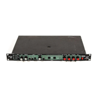
PCM 91
Proper setting of Input level on the PCM 91 is dependent on:
• Proper signal level into the analog front end to avoid signals
causing overload at the DSP input (rear panel Input Level
button),
• Proper adjustment of the signal level into the analog-to-digital
converter to optimize noise and avoid overload (front panel
INPUT knob),
• Proper setting of signal level into the digital signal processor to
optimize noise (InLvl parameter in each algorithm).
Headroom Display
The headroom display provides both
headroom and overload information from a
variety of measurement points. The meters
display analog or digital input data,
depending on the selected Audio Input
Source (Control mode 0.0).
The chart below illustrates the adjustment range that will set input
levels for both balanced and unbalanced operation.When a choice
can be made, it is best to operate at the higher amplitude end of
the recommended range to optimize noise performance.
Unbalanced Balanced
overload: >+20dBu >0dBu
acceptable: +20dBu to -2dBu 0dBu to -22dBu
too low (noisy): <-2dBu <-22dBu
Overload
The 0db (overload) indicators will light under the following
conditions:
• A/D overload
• Overload at any point in effects processing
• Input level within 1dB of maximum
For example, level buildup from certain reverberation modes can
result in overload, even when the input A/D or digital receiver data
stream is not at full scale. Such conditions are most often caused
by a combination of extreme parameter settings. Adjusting
parameter/level settings can eliminate these overload conditions.
Selecting a Digital Input Source
1. Press Control.
2. Press Up or Down until the left-most digit in the lower left-
hand corner of the display is 0.
3. Turn SELECT to 0.0 Word Clock, and turn ADJUST to display
Ext: XLR or Ext: Coax, depending on the input you are using.
HEADROOM
0dB
6
12
18
24
0 10
INPUT
 Loading...