Do you have a question about the LEYBOLD THERMOVAC TTR 211 S and is the answer not in the manual?
| Accuracy | ±15% of reading |
|---|---|
| Protection Class | IP40 |
| Sensor Type | Pirani |
| Process Connection | DN 16 ISO-KF |
| Housing Material | Aluminum |
| Supply Voltage | 15 to 30 V DC |
| Operating Temperature | 0 to +50 °C |
| Storage Temperature | -20 to 70 °C |
| Materials exposed to vacuum | Stainless steel, glass |
Provides an overview of the THERMOVAC transmitters and emphasizes safety.
Lists general technical data such as measurement range, uncertainty, and supply voltage.
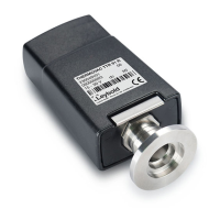
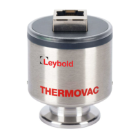
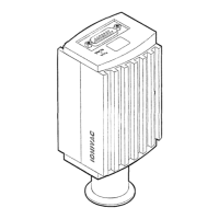
Details the measurement system, filament type, flange connection, and materials.
Covers signal output range, load resistance, and measurement signal characteristics.
Details switching threshold adjustment range, hysteresis, and contact ratings.
Describes the control input resistance and adjustment range.
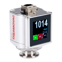
Explains the LED indicators for operation and switching threshold status.
Describes the monitor output as a 3.5 mm jack socket for signal access.
Provides dimensions and weight for the THERMOVAC transmitters.
Lists storage and operating temperature, and humidity limits.
Explains the operating principle (Pirani) and key features of the THERMOVAC transmitters.
Lists the items included in the package with the THERMOVAC transmitters.
Lists optional accessories that can be purchased for the THERMOVAC transmitters.
Provides instructions and recommendations for installing the THERMOVAC transmitters.
Details how to connect the THERMOVAC transmitters electrically to the operating unit.
Explains the requirements and connection for the power supply to the transmitter.
Describes the output signal of the transmitter and its relation to pressure.
Explains how to adjust and use the built-in switching threshold function.
Details how to access measurement and trigger settings via the monitor output jack.
Explains how to switch the output for chart recorder use.
Describes the identification resistor for transmitter type and pressure range.
Guides on connecting and powering up the THERMOVAC transmitters.
Describes the initial operation steps and LED indicators.
Explains how to interpret status messages and LED indicators during operation.
Provides common problems and their solutions for the THERMOVAC transmitters.
Outlines procedures and requirements for returning equipment to LEYBOLD for service.
States that the operating electronics do not require maintenance.
Covers maintenance procedures for the sensing cell.
Provides instructions on how to clean the sensing cell using organic solvents.
Details the steps for replacing a faulty or contaminated sensing cell.
Explains the procedure for aligning the transmitter after cell exchange or for accuracy.