Do you have a question about the LEYBOLD CERAVAC CTR 100 N and is the answer not in the manual?
Defines symbols used in the manual to convey important information about the transmitter.
Specifies the required technical training and experience for personnel handling the transmitter.
Provides essential safety instructions to be followed during installation and operation.
Outlines Leybold's liability limitations and warranty voidance conditions.
Details the full-scale measuring ranges, accuracy, supply voltage, and other specifications.
Lists part numbers with associated flange types and measurement ranges.
Lists compatible accessories such as cables and software for the transmitter.
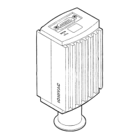
Provides physical dimensions of the transmitter with different flange types.
Describes the intended use and conditions for the transmitter.
Details prohibited uses and conditions to avoid for the transmitter.
Discusses compatibility with various process environments, including corrosive gases.
Explains the wiring for the 15-pin D-SUB connector, including power and signal lines.
Illustrates the electrical connections for the transmitter's interface.
Describes the analog voltage and RS232 digital outputs for pressure measurement.
Explains the linear analog output signal and its relation to pressure.
Procedure to reset all transmitter parameters to their original factory settings.
Details the 15-pin D-subminiature connector for power and display.
Explains the meaning of the green LED status indicator states.
Describes how to perform zero adjustment on the transmitter's analog and digital outputs.
| Operating temperature | 0 to +50 °C |
|---|---|
| Output signal | 0-10 V |
| Process connection | DN 16 ISO-KF |
| Measuring range | 1000 to 0.1 mbar |
| Supply voltage | 15 to 30 VDC |