Do you have a question about the LEYBOLD THERMOVAC TTR 91 N and is the answer not in the manual?
| Protection Class | IP40 |
|---|---|
| Housing Material | Stainless steel |
| Output Signal | 4 to 20 mA |
| Sensor Type | Pirani |
| Bakeout Temperature | without electronics: +150°C |
| Materials Exposed to Vacuum | Stainless steel, tungsten |
| Measurement Principle | Pirani / Cold Cathode (inverted magnetron) |
| Process Connection | DN 16 ISO-KF |
Explains symbols used in the manual for clarity and safety.
Specifies that only trained and experienced personnel should perform work.
Provides general safety instructions, regulations, and precautions for safe operation.
Outlines Leybold's liability limitations and warranty void conditions.
Lists detailed technical specifications, including measurement ranges, voltage, and materials.
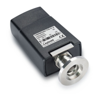
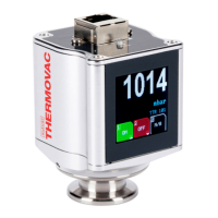
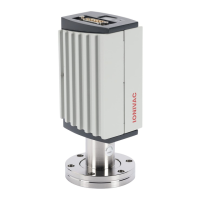
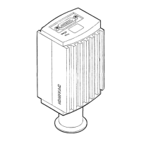
Presents dimensional drawings and measurements for different transmitter configurations.
Lists compatible accessories, cables, and spare parts with their part numbers.
Defines the intended and correct usage scenarios for the transmitter.
Details prohibited uses and environments for the transmitter.
Addresses compatibility with various process media and environments, including coated sensors.
Covers different vacuum fitting types and connection procedures.
Specifies the operational pressure range and sealing materials used.
Details the pin assignments and wiring for I/O connectors and signal connections.
Explains the functionality, connection, and operation of setpoint relays.
Explains how the transmitter provides analog voltage output for pressure readings.
Details the analog voltage output, resolution, and conversion formulas.
Discusses how different gas types affect sensor readings and presents conversion factors.
Explains the meaning of different LED colors and patterns for status indication.
Details the procedures for performing vacuum-zero/full-scale and setpoint adjustments.
Describes how to use the user switch to navigate and perform adjustments.