Do you have a question about the LEYBOLD PENNINGVAC PTR 90 N and is the answer not in the manual?
Identifies symbols for essential information and safety concerns.
Specifies work must be performed by trained and experienced personnel.
General safety guidelines for installation, operation, and handling of the transmitter.
Outlines conditions under which liability is disclaimed and warranty is voided.
Explains the principles of MEMS Pirani and cold cathode sensor elements.
Lists various industrial, research, and development applications for the transmitter.
Environmental guidelines for the proper disposal of the transmitter at its end-of-life.
Detailed specifications including measurement ranges, accuracy, power, and materials.
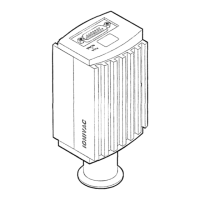
Provides detailed dimensional drawings for different PENNINGVAC transmitter models.
Lists available accessories and replacement parts with their corresponding part numbers.
Defines the intended use and operational environment for the transmitter.
Lists prohibited uses, environments, and modifications for the transmitter.
Discusses transmitter compatibility with various processes and potential issues like contamination.
Guidelines for selecting and installing vacuum fittings, ensuring cleanliness and proper sealing.
Details pin assignments and wiring diagrams for different connector types.
Explains the function, rating, and handling of setpoint relays, including inductive load precautions.
Describes how the transmitter provides pressure measurement via analog voltage or digital interfaces.
Details the cold cathode ignition process, delay times, and LED status indicators.
Explains the analog voltage output, conversion formulae, and provides a data table.
Discusses how gas type affects readings and provides conversion factors for different gases.
Explains the meaning of different LED colors and flash patterns for transmitter status.
Details procedures for zero and full-scale adjustments for MEMS Pirani and setpoint adjustments.
Describes how to use the user switch for adjustments and the resulting LED feedback.
Outlines the menu structure and functions for the integrated touch display.
Details procedures for cleaning and replacing cold cathode components.
| Supply Voltage | 24 V DC |
|---|---|
| Measurement Principle | Cold cathode (Penning) |
| Operating Temperature | 0 to 50 °C |
| Protection Class | IP 40 |
| Output Signal | 0-10 V |
| Connector | 9-pin D-sub |
| Mounting Flange | DN 25 ISO-KF |
| Accuracy | ±30% of reading |