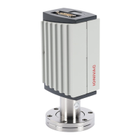
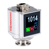
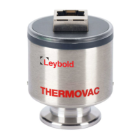
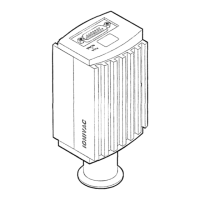
The Leybold CERAVAC® Transmitter CTR 100 N is a vacuum measurement device designed for a variety of applications in semiconductor, analytical, and coating industries. It offers a four-decade measurement range based on the electrical capacitance between a diaphragm and a fixed electrode. A key feature of this sensor technology is that its output is independent of the process gas composition, eliminating the need for gas correction factors. The diaphragm and sensor are constructed entirely from nickel alloy, providing resistance to corrosion and oxidation.
The transmitter can operate as a standalone unit or integrate with a suitable controller. Its primary communication method is a 0-10 VDC analog output signal, which can be interfaced with external analog equipment for pressure readout or control. Additionally, it includes an RS232 digital communication interface for setting transmitter parameters and real-time pressure measurement.
Function Description:
The CTR 100 N measures pressure by detecting changes in electrical capacitance. As process pressure changes, the thin metal diaphragm shifts its position relative to a patterned electrode, causing a proportional change in electrical capacitance. This capacitance change is then converted into a pressure reading. The device is designed to maintain a low reference pressure on one side of the diaphragm using a getter pump, ensuring accurate differential pressure measurement.
Usage Features:
- Measurement Range: Provides a four-decade measurement range for various vacuum applications.
- Gas Independence: The measurement is independent of the process gas composition, simplifying operation as no gas correction factors are required.
- Output Signals: Offers both a 0-10 VDC analog output for interfacing with external analog equipment and an RS232 digital interface for parameter setup and real-time data.
- Corrosive Environments: The sensor's nickel alloy construction allows for extended use in corrosive environments, although frequent zeroing may be necessary in such applications.
- Mounting Flexibility: Can be mounted in any orientation without compromising accuracy or lifetime, except for the inlet port facing upwards, which is not recommended due to potential contamination. Transmitters with ranges of 1 Torr and less may require zero adjustment if mounted horizontally to compensate for gravity effects on the sensor diaphragm.
- Process Compatibility: Intended for use in non-condensing process environments. It can be used with aggressive gases like chlorine and fluorine, but users should anticipate drift and more frequent zeroing.
- Overpressure Resistance: The sensor element is robust and can withstand continuous pressure cycles and instant venting to atmospheric pressure without damage, provided the maximum overpressure specification is not exceeded.
- Vibration Resistance: Can withstand mechanical vibrations for short periods without damage, though output signal variations may occur due to diaphragm resonance.
- Zero Adjustment: Features a zero pushbutton for periodic zeroing of the output to maintain measurement accuracy. This can be done at pressures less than 20% of the full-scale measurement range. Multiple adjustment modes are available, including a ramp function for fine-tuning the zero to a known reference pressure or to achieve a slightly positive zero for analog/digital converters that require 0-10 VDC input.
- LED Status Indicator: A green LED provides visual feedback on the transmitter's status: no indication (mains power off), solid (normal operation), or blinking (other mode, error, or over/under-range).
- Factory Default Reset: Allows users to reset all transmitter parameters to original factory settings by pressing and holding the ZERO pushbutton while reconnecting mains power.
Maintenance Features:
- Contamination Prevention: Users are advised to locate and orient the transmitter to minimize contamination entry into the sensor, as contamination can cause zero drift.
- Cleaning: The sensor element cannot be cleaned using solvents if contaminated with liquids like vacuum pump oil, as this is likely to cause permanent damage.
- Electrical Connections: Requires proper electrical connections with strain relief and shielded cables to ensure optimal performance and reduce stress on connectors. A low impedance electrical connection to the grounded vacuum system is necessary for shielding against electromagnetic sources.
- Bakeout Limitations: Bakeout of the entire transmitter is not recommended due to potential damage to the electronics. Only the fitting (not including the inlet tube) may be baked up to 50°C.
- Calibration: Leybold recommends checking the transmitter's calibration against a known pressure reference approximately every 12 months. Zeroing frequency depends on the application, with more frequent zeroing needed for exposure to atmospheric pressure or corrosive/condensable gases.
- Non-Volatile Memory: All transmitter parameters, including user calibration, are stored internally in non-volatile memory and retained after power is shut off.
- Disposal: Manufactured according to the RoHS directive. At the end of its life, the transmitter should be disposed of at an appropriate collection point for recovery or recycling, not in the normal unsorted waste stream.