Due to our policy of continuous product innovation, some specications may change without notication.
© LG Electronics U.S.A., Inc., Englewood Cliffs, NJ. All rights reserved. “LG ” is a registered trademark of LG Corp.
19
Product Data
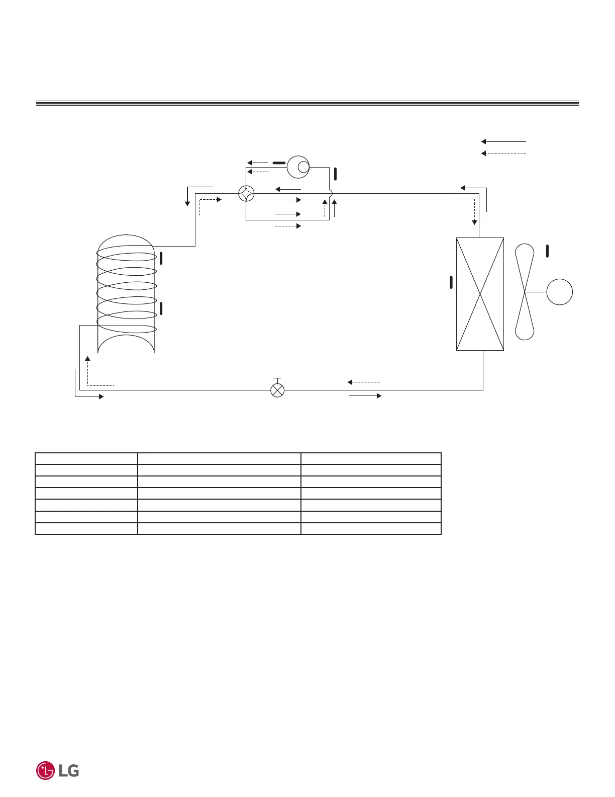
REFRIGERANT FLOW DIAGRAM
Figure 8: APHWC501D, APHWC801D, APHWC501L, APHWC801L Heat Pump Water Heater Refrigerant Flow Diagram.
M
Compressor
Heating
Defrost
Th1
Th4
Th5
Th3
Th2
Th6
Water Tank
Heat
Exchanger
(Condenser)
Heat
Exchanger
(Evaporator)
Electronic Expansion Valve (EEV)
Table 7: Heat Pump Water Heater Thermistors.
Thermistor Description PCB Connector
Th1 Discharge Pipe Temperature Thermistor CN_TH2
Th2 Evaporator Temperature Thermistor CN_TEMP_AIR
Th3 Indoor Air Temperature Thermistor CN_TEMP_AIR
Th4 Suction Pipe Temperature Thermistor CN_TH1
Th5 Upper Water Tank Temperature Thermistor CN_TANK_U
Th6 Lower Water Tank Temperature Thermistor CN_TANK_D
 Loading...