12
ENGLISH
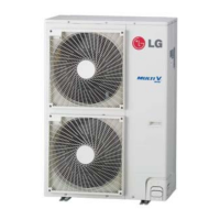
Cautions for Handling Service Valve
- The service valves are closed at shipment from the factory
How to Use the Shut-Off Valve
Use hexagonal wrenches 4mm or 6mm
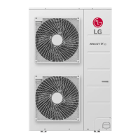
Opening the valve
- Place the hexagon wrench on the valve bar and turn counter-clock-
wise.
- Stop when the valve bar no longer turns. It is now open.
Closing the valve
- Place the hexagon wrench on the valve bar and turn clockwise.
- Stop when the valve bar no longer turns. It is now closed.
CAUTION
Make sure to keep the valve open during operation.
!
Refrigerant pipe connection torque
Pipe external
diameter
6.35mm
(1/4")
9.52mm
(3/8")
12.7mm
(1/2")
15.88mm
(5/8")
Torque
180~250
kgf.cm
340~420
kgf.cm
550~660
kgf.cm
630~820
kgf.cm
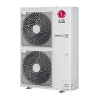
The names of parts of the service valve are shown in the figure.
Since the side boards may be deformed if only a torque wrench is
used when loosening or tightening flare nuts, always lock the shut-off
valve with a wrench and then use a torque wrench.
Do not place wrenches on the valve cover.
Do not apply force on the valve cover, this may result in a refrigerant
leak.
1. Service point
2. Shut-off Valve
3. Filed piping connection
4. Valve cover
1. Spanner
2. Torque wrench
Direction to open Direction to open
<Liquid pipe> <Gas pipe>
CAUTION
1 Use the following materials for refrigerant piping.
• Material: Seamless phosphorous deoxidized copper pipe
• Wall thickness : Comply with the relevant local and national regu-
lations for the designed pressure 3.8MPa. We
recommend the following table as the minimum
wall thickness.
2 Commercially available piping often contains dust and other materi-
als. Always blow it clean with a dry inert gas.
3 Use care to prevent dust, water or other contaminants from enter-
ing the piping during installation.
4 Reduce the number of bending portions as much as possible, and
make bending radius as big as possible.
5 Always use the branch piping set shown below, which are sold sep-
arately.
6 If the diameters of the branch piping of the designated refrigerant
piping differs, use a pipe cutter to cut the connecting section and
then use an adapter for connecting different diameters to connect
the piping.
7 Always observe the restrictions on the refrigerant piping (such as
rated length, difference in height, and piping diameter).
Failure to do so can result in equipment failure or a decline in heat-
ing/cooling performance.
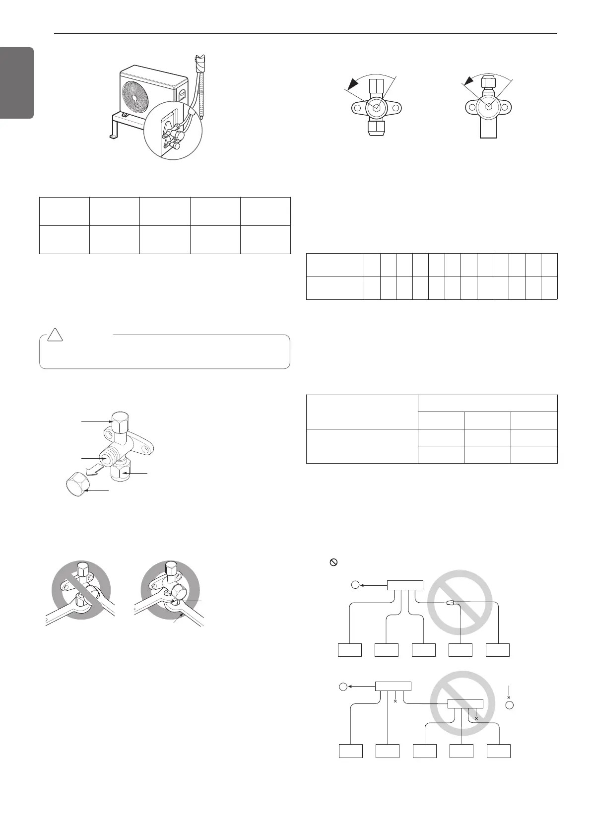
8 A second branch cannot be made after a header. (These are shown
by .)
Outer diameter
[mm]
6.35 9.52 12.7 15.88 19.05 22.2 25.4 28.58 31.8 34.9 38.1 41.3
Minimum
thickness [mm]
0.8 0.8 0.8 0.99 0.99 0.99 0.99 0.99 1.1 1.21 1.35 1.43
Y branch
Header
4 branch 7 branch 10 branch
ARBLB01621, ARBLB03321,
ARBLB07121, ARBLB14521,
ARBLB23220
ARBL054 ARBL057 ARBL1010
ARBL104 ARBL107 ARBL2010
 Loading...