13
ENGLISH
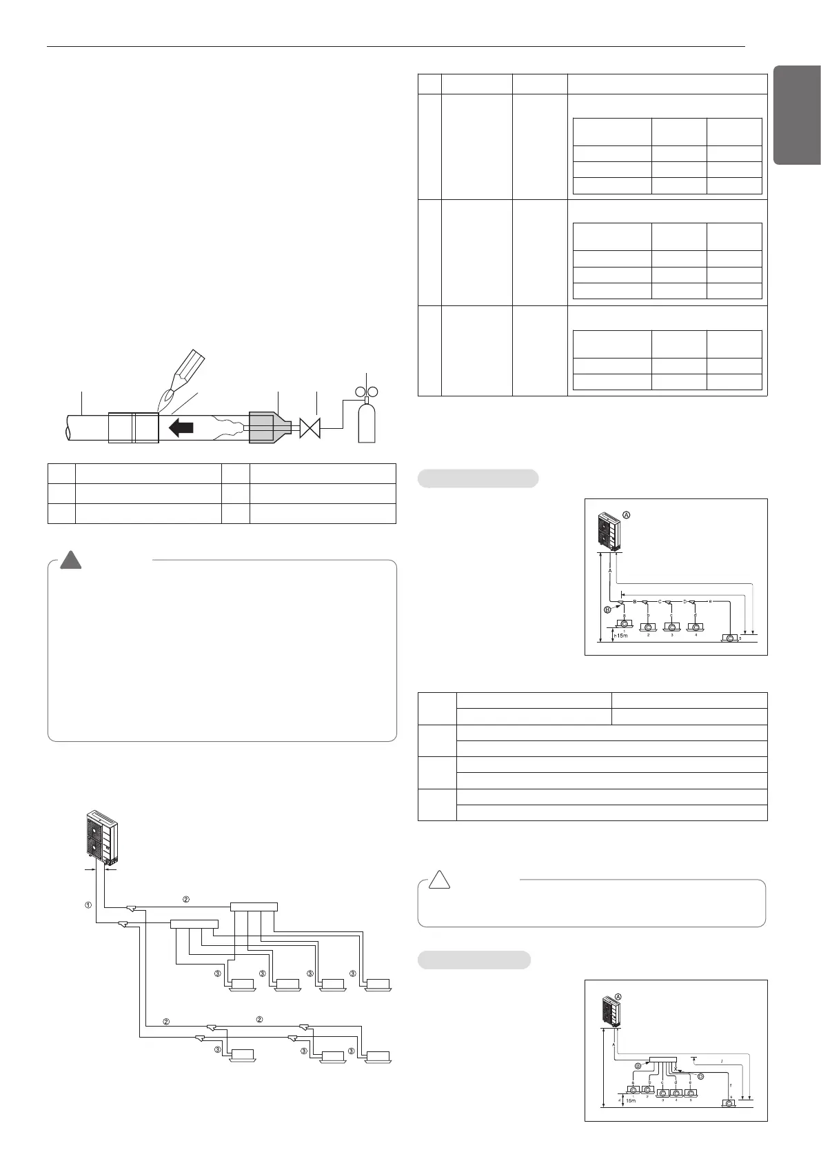
No. Piping parts Name Selection of pipe size
①
Outdoor unit
↓
1st branching
section
Main pipe
②
Branching
section
↓
Branching
section
Branching
pipe
③
Branching
section
↓
Indoor unit
Indoor unit
connecting
pipe
9 The Multi V will stop due to an abnormality like excessive or insuffi-
cient refrigerant. At such a time, always properly charge the unit.
When servicing, always check the notes concerning both the piping
length and the amount of additional refrigerant.
10 Never use refrigerant to perform an air purge. Always evacuate
using a vacuum pump.
11 Always insulate the piping properly. Insufficient insulation will re-
sult in a decline in heating/cooling performance, drip of conden-
sate and other such problems.
12 When connecting the refrigerant piping, make sure the service
valves of the Outdoor Unit is completely closed (the factory set-
ting) and do not operate it until the refrigerant piping for the Out-
side and Indoor Units has been connected, a refrigerant leakage
test has been performed and the evacuation process has been
completed.
13 Always use a non-oxidizing brazing material for brazing the parts
and do not use flux. If not, oxidized film can cause clogging or
damage to the compressor unit and flux can harm the copper pip-
ing or refrigerant oil.
3
2
1
45
6
1 Refrigerant piping 4 Taping
2 Pipe to be brazed 5 Valve
3 Nitrogen 6 Pressure-reducing valve
WARNING
• When installing and moving the air conditioner to another site,
be sure to make recharge refrigerant after perfect evacuation.
- If a different refrigerant or air is mixed with the original refrig-
erant, the refrigerant cycle may malfunction and the unit may
be damaged.
- After selecting diameter of the refrigerant pipe to suit total ca-
pacity of the indoor unit connected after branching, use an ap-
propriate branch pipe set according to the pipe diameter of the
indoor unit and the installation pipe drawing.
• Do not use anti-oxidants when brazing the pipe joints. Residue
can clog pipes and break equipment.
!
Selection of Refrigerant Piping
Allowable Length/Height Difference of Refrig-
erant Piping
Outdoor unit
Gas pipe
Main pipe
Liquid pipe
Branching
pipe
Branching
pipe
Indoor unit
Outdoor unit capacity
[kW(Btu/h)]
Liquid pipe
[mm(inch)]
Gas pipe
[mm(inch)]
4HP Ø9.52(3/8) Ø15.88(5/8)
5HP Ø9.52(3/8) Ø15.88(5/8)
6HP Ø9.52(3/8) Ø19.05(3/4)
Indoor unit capacity
[kW(Btu/h)]
Liquid pipe
[mm(inch)]
Gas pipe
[mm(inch)]
≤ 5.6(19,100)
Ø6.35(1/4) Ø12.7(1/2)
< 16.0(54,600) Ø9.52(3/8) Ø15.88(5/8)
< 22.4(76,400) Ø9.52(3/8) Ø19.05(3/4)
Indoor unit capacity
[kW(Btu/h)]
Liquid pipe
[mm(inch)]
Gas pipe
[mm(inch)]
≤ 5.6(19,100)
Ø6.35(1/4) Ø12.7(1/2)
< 16.0(54,600) Ø9.52(3/8) Ø15.88(5/8)
Size of main pipe
Pipe size of between branching sections
Connecting pipe size of indoor unit
Y Branch Method
Example : 5 Indoor Units con-
nected
Ⓐ : Outdoor Unit
Ⓑ : 1st branch (Y branch)
Ⓒ : Indoor Units
L150m
H 50m
l 40m
Total pipe length = A+B+C+D+a+b+c+d+e ≤ 300m
* : Assume equivalent pipe length of Y branch to be 0.5m, that of
header to be 1m, calculation purpose.
L
Longest pipe length Equivalent pipe length(*)
A+B+C+D+e ≤ 150m A+B+C+D+e ≤ 175m
l
Longest pipe length after 1st branch
B+C+D+e ≤ 40m
H
Difference in height(Outdoor Unit ÷ Indoor Unit)
H ≤ 50m ( 40m : Outdoor Unit is lower than Indoor Units)
h
Difference in height (Indoor Unit ÷ Indoor Unit)
h ≤ 15m
Header Method
Example : 6 Indoor Units con-
nected
Ⓐ : Outdoor Unit
Ⓑ : 1st branch
Ⓒ : Indoor Units
Ⓓ : Sealed piping
L 150m
H 50m
40m
CAUTION
Indoor Unit should be installed at lower position than the header.
!
 Loading...