3 Phase 4 Wires
Power supply
60Hz 380V
Power supply
1 Phase 60Hz
220V
Power supply switch
(Switch fuse : ELCB)
Power supply switch
(Switch fuse)
(Main Switch)
Pull Box(Installer Option)
3 Phase 4 Wires Power line(R, S, T, N)
Single Phase of power supply line(L, N)
Communication line (3 line): Wired remote control
Communication line (2 shield line):
Between Indoor Unit and Outdoor Unit
WARNING
• Indoor Unit ground Lines are required for preventing electrical shock
accident during current leakage,
Communication disorder by noise effect and motor current leakage
(without connection to pipe).
• Don't install an individual switch or electrical outlet to disconnect
each of indoor unit separately from the power supply.
• Install the main switch that can interrupt all the power sources in an
integrated manner because this system consists of the equipment
utilizing the multiple power sources.
• If there exists the possibility of reversed phase, lose phase, mo-
mentary blackout or the power goes on and off while the product is
operating, attach a reversed phase protection circuit locally.
Running the product in reversed phase may break the compressor
and other parts.
!
WARNING
• Main PCB power should be reset in order to recognize the changed
function after handling the DIP switch for configuration of additional
functions.
• Main PCB power should be reset after resetting the DIP switch for
cancellation of additional function
• Please configure DIP switch properly. Otherwise, It can overstrain
product during operation.
!
3Ø, 60Hz
u Example Connection of Communication Cable
[BUS type] [STAR type]
- Connection of communication
cable must be installed like
below figure between indoor
unit to outdoor unit.
- Abnormal operation can be
caused by communication de-
fect, when connection of com-
munication cable is installed like
below figure(STAR type).
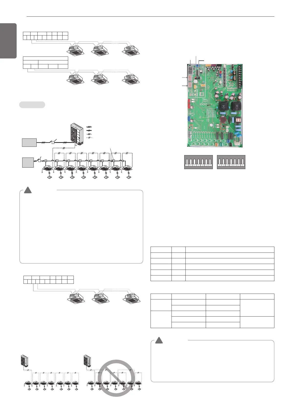
Location of DIP Switch (U3 Chassis, 2 Fan
Model)
Main PCB
1 When outdoor unit is powered on after configuring the DIP switch,
proper input of configuration value can be verified through 7-Seg-
ment.
2 This function is shown only for 2 seconds after turning on the
power.
Verification of outdoor unit configuration
- After power is turned on, number are shown on
7-Segment consecutively
- These numbers show the configuration status
In case of 3Ø, 5HP model
 Loading...