LED01M (Red)
LED02M (Green)
SW02N
Auto Addressing
SW01N
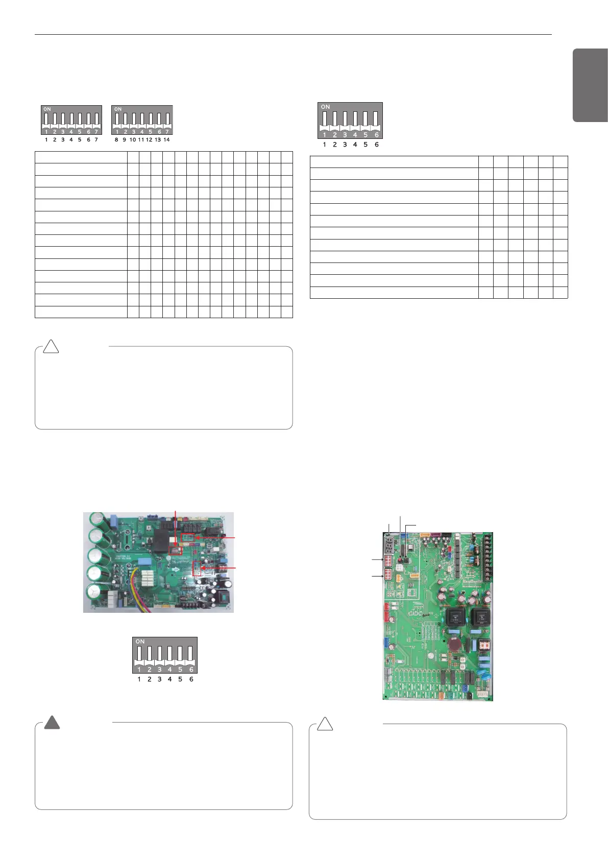
Configuration of DIP Switch (U3 Chassis, 2
Fan Model)
Location of DIP Switch (U4 Chassis, 1 Fan
Model)
Main PCB
Configuration of DIP Switch (U4 Chassis, 1 Fan
Model)
1 2 3 4 5 6 7 8 9 10 11 12 13 14
l5
5l
ll l
ll l l
ll5
5l5
55l
5ll
ll
l5
ll
55 l
ll
Short Pipe Length
Long Pipe Length
Refrigerant Auto Charging
Refrigerant Checking
Cool/Heat Selector
Snow (Heat Pump model)
Forced Defrosting (Heat Pump model)
Snow + Forced Defrosting (Heat Pump model)
Night Silent Operation
Pump Down
Pump Out (Heat Pump model)
Forced Oil Return
Vacuum Mode
1 2 3 4 5 6
l
l
l
ll
ll
ll
l
ll
l
l
ll
Short Pipe Length
Long Pipe Length
Cool/Heat Selector
Forced Oil Return
Forced Defrosting
Vacuum Mode
Pump Down
Pump Out
Night Silent Operation Step 1
Night Silent Operation Step 2
Night Silent Operation Step 3
CAUTION
• “X” mark means DIP switch must be off, Otherwise the function
may not perates correctly.
• If each DIP switch doesn’t set correctly, unit will operate abnor-
mally.
• In case of proceeding test run, start after checking if all indoor unit
is off.
!
CAUTION
In replacement of the indoor unit PCB, always perform auto address
setting again.
- If power supply is not applied to the indoor unit, operation error oc-
curs.
- Auto addressing is only possible on the main PCB
- Auto addressing has to be performed after 3 minutes to improve
communication.
!
<Initial shipping condition of DIP Switch>
WARNING
• Main PCB power should be reset in order to recognize the changed
function after handling the DIP switch for configuration of additional
functions.
• Main PCB power should be reset after resetting the DIP switch for
cancellation of additional function
• Please configure DIP switch properly. Otherwise, It can overstrain
product during operation
!
Automatic Addressing (U3 Chassis, 2 Fan
Model)
The address of indoor units would be set by auto addressing
- Wait for 3 minutes after applying power supply
(outdoor unit, indoor unit).
- Press the switch of the outdoor unit (SW02V) for 5 seconds.
- A "88" is indicated on 7-segment LED of the outdoor unit PCB.
- For completing addressing, 2~7 minutes are required depending on
numbers of indoor unit connection set.
- Numbers of indoor unit connection set whose addressing is com-
pleted are indicated for 30seconds on 7-segment LED of the outdoor
unit PCB.
- After completing addressing, address of each indoor unit is indicated
on the wired remote control display window. (CH01, CH02,
CH03, ............. CH06: Indicated as numbers of indoor unit connection
set.)
SW01B
(DIP S/W)
SW02B
(DIP S/W)
7 - Segment
SW02V
Auto addressing
SW01V
Data confirm
 Loading...