Purpose
Judgment of the IPM part fault of
PCB assembly.
Items for checking
1. Judgment of damage of IGBT
2. Checking the soldering state
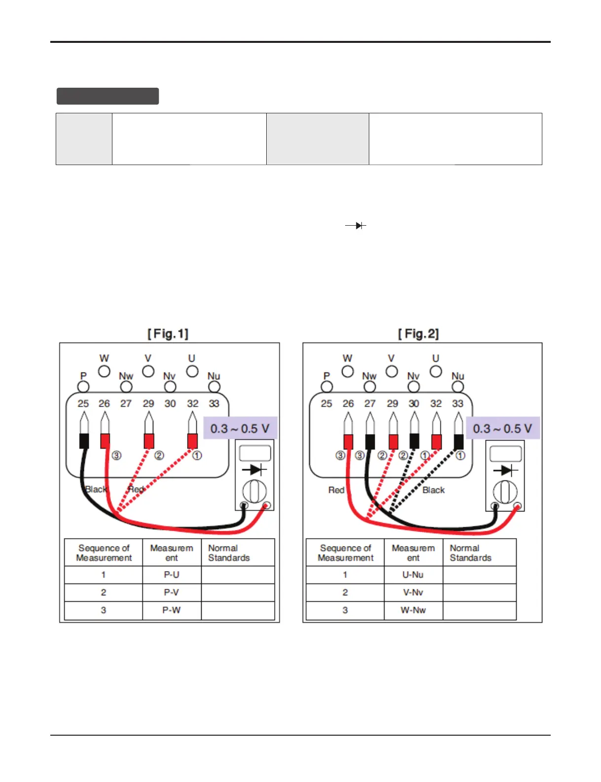
■ How to check IPM IGBT (Diode Mode)
1. Remove the connector from PCB.
2. Set the Multi-Tester as Diode Voltage Measurement Mode. (
)
3. Measure the voltages of P~U / P~V / P~W as shown in Fig. 1.
4. Measure the voltages of U~Nu / V~Nv / W~Nw as shown in Fig. 2.
5. If the measurements are significantly different from the levels shown in the figures, the IPM is deemed to
be damaged.
IPM Check
0.3 V~0.5 V
0.3 V~0.5 V
0.3 V~0.5 V
0.3 V~0.5 V
0.3 V~0.5 V
0.3 V~0.5 V
 Loading...