Do you have a question about the LG FFH-286A and is the answer not in the manual?
Guidelines for safe and proper servicing of the device.
Specific instructions for handling the sensitive pick-up component.
Precautions for servicing CD player components, including static electricity.
Measures to prevent damage from electrostatic discharge to sensitive components.
Explanation of hazard symbols used in the manual for safety awareness.
Procedures for aligning and calibrating the system's circuits.
Flowchart for diagnosing and resolving common malfunctions in the unit.
Illustrations of critical signal waveforms for troubleshooting and alignment.
Block diagram and pin definitions for the 5-channel motor driver IC.
Internal block diagram and description of the voltage regulator.
Block diagram of the PLL frequency synthesizer IC.
Block diagram of the AM/FM IF and MPX IC.
Electrical characteristics table for the KIA78R12 voltage regulator.
Description of the 2-channel head switch for radio cassette recorders.
Block diagram and pin description for the serial-to-parallel driver IC.
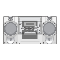
Exploded view of the unit's main chassis and external cabinet components.
Exploded view of the optional auto-stop tape deck mechanism.
Exploded view of the auto-reverse tape deck mechanism.
Exploded view of the CD playback mechanism and its parts.
| Brand | LG |
|---|---|
| Model | FFH-286A |
| Category | Stereo System |
| Language | English |