- 53 -
Copyright © 2009 LG Electronics. Inc. All right reserved.
Only for training and service purposes
LGE Internal Use Only
4. RF Circuit Technical Brief
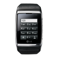
[Figure 4.2.5-3] GD910 Front End Control Logic Table
4.3 WCDMA Part
The single-chip transceiver is designed to fulfill the W-CDMA UTRA FDD system requirements for bands I, II, III,
IV, V, VI and IX. It contains all active circuits required to simultaneously modulate an analog W-CDMA I/Q
signal to the TX RF frequency and demodulate a RX RF W-CDMA signal to an I/Q baseband signal.
4.3.1 WCDMA Receiver
The direct conversion receiver for each band consists of:
•fully differential signal path
•RF low noise amplifier (LNA2)
•I/Q demodulator including LO buffer and I/Q divider
•LO including on-chip VCO and synthesizer
•DC offset compensation without external components
•analog channel filter including auto calibration circuit (w/o external components)
•programmable gain control (PGC) controlled by 3-wire bus programming and gain setting unit on-chip
•allpass filter (auto calibrated)
•configurable output drivers (programmable DC voltages and driver currents for different load impedances)
RX Front-End
An external low noise amplifier as well as duplex and interstage filters are needed to form a complete receive
chain for each band.
 Loading...