Do you have a question about the LG GR-642APA and is the answer not in the manual?
Procedure for recharging refrigerant in the compressor system.
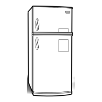
Detailed specifications for the GR-642* refrigerator model.
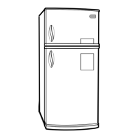
Detailed specifications for the GR-702* refrigerator model.
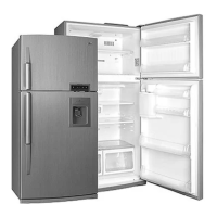
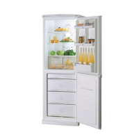
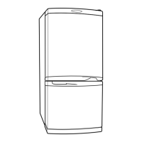
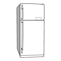
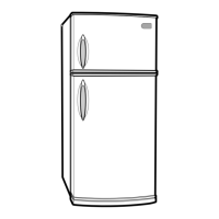
Illustrates and labels various parts of the refrigerator.
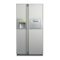
Details on filling, using, and cleaning the water dispenser.
Instructions for cleaning the water dispenser grille, drip tray, and tank.
Steps for disassembling the freezer and refrigerator doors.
Steps for removing and disconnecting the door switch.
Steps for removing the fan and fan motor assembly.
Steps for removing the defrost control assembly.
Steps for replacing the freezer and refrigerator lamps.
Steps for removing the control box.
Details on the compressor's role, composition, and usage notes.
Explanation of the PTC starter's composition, role, and usage.
Circuit diagram showing PTC starter application.
Definition and role of the Over Load Protector (OLP).
Troubleshooting steps for the compressor and electric components.
Troubleshooting steps for PTC and OLP components.
Troubleshooting guide for other electric components.
A chart for diagnosing and remedying common complaints.
Troubleshooting chart for refrigerating cycle issues.
Details on materials and procedures for the refrigerating cycle control.
Overview of the refrigerator's functional modes and controls.
Explanation of basic operational modes and button functions.
Explanation of the Super Cool feature and its operation.
Describes the function of front and rear LEDs.
Details on the variable speed fan control in the freezer.
Explanation of the open door alarm and buzzer function.
Describes the buzzer sound function.
Details on the double cooling fan operation in the refrigerator.
Explanation of the defrosting process and timing.
Describes sequential operation of components during startup or test.
Explains the error diagnostic mode and error codes.
Details on entering and operating the product's test modes.
Diagram and explanation of the power supply circuit for the PCB.
Explains the oscillation circuit for the MICOM.
Describes the reset circuit for initializing functions.
Circuitry for driving loads, buzzer, and detecting door status.
Checks the conditions for buzzer operation.
Checks the circuit for detecting door status.
Explains temperature sensor circuits and their states.
Circuit for detecting switch inputs, including test S/W.
Circuits for temperature compensation and over/under cooling.
Circuit for key input and display light activation.
Explains the dispenser pump motor operation circuit.
Steps to diagnose and fix power source problems.
Steps to diagnose and fix cooling failures.
Diagnosing and fixing poor refrigerator temperature.
Diagnosing and fixing defrosting failures.
Diagram showing the layout of the Main PCB and its components.
List of replaceable parts with their specifications and part numbers.
Parts list specifically for the PWB assembly and display components.
Exploded view of the refrigerator showing parts placement.
Exploded view of the dispenser assembly and its parts.
| Energy Rating | A+ |
|---|---|
| Dimensions (H x W x D) | 160.5 x 60.5 x 63.5 cm |
| Weight | 78 kg |
| Color | Silver |
| Defrosting Type | Manual Defrost (Freezer), Automatic Defrost (Refrigerator) |
| Defrost System | Manual Defrost (Freezer), Automatic Defrost (Refrigerator) |