EasyManua.ls Logo

LG GR-642AVP User Manual

LG GR-642AVP
43 pages
To Next Page IconTo Next Page
Page #1 background imageLoading...
Page #1 background image
CAUTION
BEFORE SERVICING THE UNIT, READ THE "SAFETY
PRECAUTIONS" IN THIS MANUAL.
MODEL: GR-642AVP
REFRIGERATOR
SERVICE MANUAL
COLOR: SUPER WHITE
http://biz.lgservice.com
Ref.No.
GR-642AVP
Question and Answer IconNeed help?

Do you have a question about the LG GR-642AVP and is the answer not in the manual?

LG GR-642AVP Specifications

General IconGeneral
BrandLG
ModelGR-642AVP
CategoryRefrigerator
LanguageEnglish

Summary

SAFETY PRECAUTIONS

SERVICING PRECAUTIONS

Air Recharging in Compressor

Procedure for testing and refilling the refrigeration system with R-134a.

SPECIFICATIONS

GR-S642P Specifications

Technical details and capacity for model GR-S642P.

GR-S702P Specifications

Technical details and capacity for model GR-S702P.

PARTS IDENTIFICATION

Feature Chart

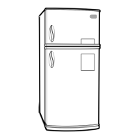
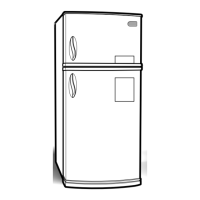
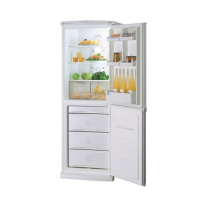
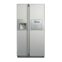
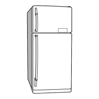
Visual representation of refrigerator components and their locations.

WATER DISPENSER OPERATION

Putting The Water In The Water Tank

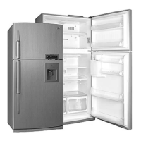
Steps for filling the water tank and securing it.

Drinking Operation

Instructions for dispensing water using the lever.

WATER DISPENSER CLEANING

Cleaning Grille, Drip Tray, and Water Tank

Procedure for cleaning the water dispenser components with mild detergent.

DISASSEMBLY

Door Disassembly

Steps to remove freezer and refrigerator doors.

Door Switch and Fan Motor Disassembly

Procedures for removing the door switch and fan motor assembly.

DEF' CONTROL ASSY, LAMP, AND CONTROL BOX-R

Defrost Control Assembly Removal

Steps to remove and replace the defrost control assembly.

Lamp Replacement

Instructions for replacing freezer and refrigerator lamps.

Control Box-R Removal

Procedure for removing the control box-R.

ADJUSTMENT

Compressor Role and Notes

Explanation of compressor function, composition, and usage precautions.

PTC-STARTER Function and Usage

Details on PTC-starter composition, role, circuit, and precautions.

OLP (OVER LOAD PROTECTOR) Function

CIRCUIT DIAGRAM

TROUBLESHOOTING

Compressor and Electric Components Troubleshooting

Diagnostic steps for compressor and related electric parts.

PTC AND OLP Troubleshooting

ANOTHER ELECTRIC COMPONENTS Troubleshooting

SERVICE DIAGNOSIS CHART

REFRIGERATING CYCLE Troubleshooting Chart

General Control of Refrigerating Cycle

DESCRIPTION OF FUNCTION & CIRCUIT OF MICOM

MICOM Functionality Overview

Overview of the MICOM control system and its operational modes.

Super Cool Mode Operation

LED Indicators and Fan Control

Buzzer Sound, Cooling Fan Control, and Defrosting

Sequential Operation of Electric Components

Error Diagnostic Mode

Test Mode Operation

PCB FUNCTION

Power Circuit Analysis

Diagram and explanation of the main power supply circuit for the PCB.

Oscillation and Reset Circuits

Load/Buzzer Drive and Door Detection

Temperature Sensor Circuit

Switch Input and Temperature Compensation Circuits

Key Button Input and Display Light Circuit

Dispenser Pump Motor Operation Circuit

RESISTANCE SPECIFICATION OF SENSOR

TROUBLE SHOOTING

Power Source Issues

Troubleshooting steps for power source problems and LED indicators.

Cooling Performance Issues

Diagnostic procedures for no cooling or poor cooling performance.

Freezer Temperature Issues

Troubleshooting steps for incorrect freezer temperature.

Refrigerator Temperature Issues

Defrosting Issues

MAIN PWB ASS'Y AND PARTS LIST

Main PWB Assembly Diagram

Schematic of the main Printed Circuit Board assembly.

Replacement Parts List

PWB Assembly Display and Parts List

PWB DIAGRAM

EXPLODED VIEW & REPLACEMENT PARTS LIST

Exploded View of Refrigerator Components

Diagram showing the assembly of various refrigerator parts with numerical labels.

Related product manuals