Do you have a question about the LG LDC22720 and is the answer not in the manual?
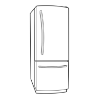
Instructions for removing and disassembling refrigerator doors.
Procedure for removing and disconnecting the door switch.
Steps to remove and replace the fan and fan motor.
Procedure for accessing and replacing the defrost control assembly.
Instructions for replacing refrigerator and freezer compartment lamps.
Steps for removing and accessing the refrigerator control box.
Procedure for removing and disconnecting the multi duct assembly.
Details on compressor role, composition, and handling precautions.
Explanation of PTC-starter composition, role, and usage notes.
Definition, role, and internal structure of the overload protector.
Step-by-step guide for removing the PTC cover.
Troubleshooting flowcharts for compressor and electrical parts.
Diagnostic steps for PTC-starter and Overload Protector issues.
Diagnosing issues with other electrical components like fans and heaters.
A chart correlating complaints with points to check and remedies.
Troubleshooting chart for refrigeration cycle issues like leakage and clogs.
Explanation of basic refrigerator and freezer temperature controls.
Details on freezer fan motor operation and speed control.
Functionality and operation of the ICE PLUS feature.
Description of the automatic shut-off feature for the refrigerator lamp.
Explanation of the door open alarm feature and its sound patterns.
Description of the buzzer sound produced by button presses.
Conditions and logic for the automatic defrosting cycle.
Sequence of electrical component activation during power-on and testing.
Overview of the automatic defect diagnosis and error code display.
Instructions for entering and operating various test modes for diagnostics.
Schematic and voltage details of the power supply circuit.
Circuit diagram for the MICOM's clock generation.
Circuit diagram for initializing the MICOM upon power supply.
Circuits for load drive, buzzer, and door open detection.
Circuit for cooling motor driving in the machine room.
Conditions for checking the buzzer drive functionality.
Circuit diagram for refrigerator, freezer, and defrost temperature sensors.
Circuit for regulating refrigerator temperature using a stepping motor damper.
Circuits for temperature compensation and over/under cooling adjustments.
Circuit for inputting button commands and activating display lights.
Diagram showing the layout of the main printed wiring board.
List of replacement parts for the main PWB with part numbers.
List of parts for the PWB display assembly.
Detailed schematic of the main PWB assembly.
Exploded view and part list for the refrigerator's case components.
Exploded view and part list for freezer compartment components.
Exploded view and part list for refrigerator compartment components.
Exploded view and part list for refrigerator and freezer door components.
Exploded view and part list for ice maker components.
| Type | French Door |
|---|---|
| Energy Star Certified | Yes |
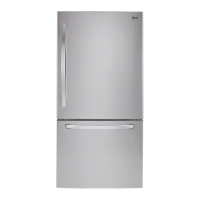
| Color | Stainless Steel |
| Ice Maker | Yes |
| Water Dispenser | Yes |
| Energy Star Qualified | Yes |
| Door Finish | Smooth |
| Width | 32.75 in. |