4. TROUBLE SHOOTING
- 169 -
Copyright © 2012 LG Electronics. Inc. All right reserved.
Only for training and service purposes
LGE Internal Use Only
c. Charging current ow check point
- Micor USB connector
- PM8921 USB VBUS_IN ( Internal OVP )
- PM8921 DC_OUT -> DC_IN
- Load Switch
- Battery
d. Charging Procedure
- Connect Travel Adaptor (Charging Cable) to Micro USB
connector.
- Current ow to PM8921 USB_VBUS_IN to be protected
from over voltage
- Current from PM8921 DC_OUT to DC_IN meanwhile,
PM8921 indicate charger insertion
- Current from charging IC ows to system and battery
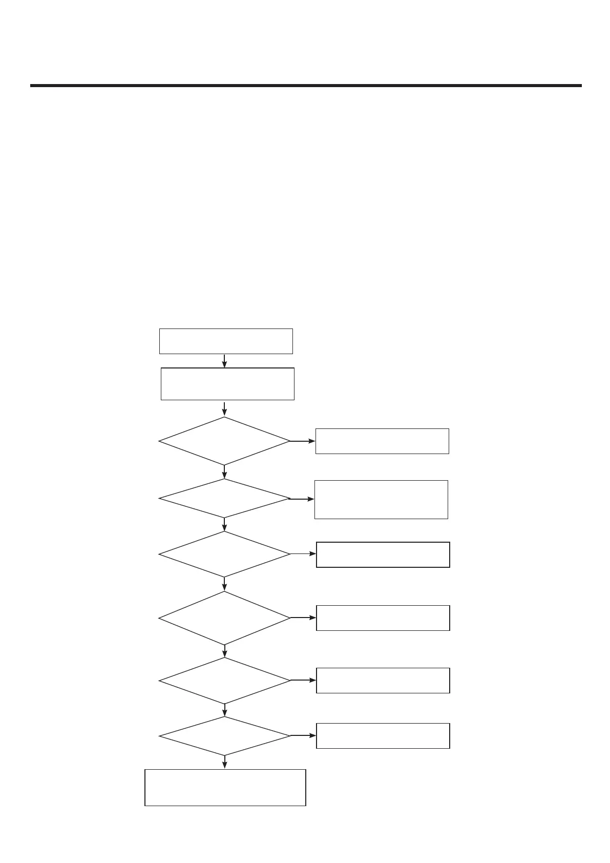
e. Troubleshooting Setup
- Connect TA to LGE960(with battery)
f. Troubleshooting Procedure
- Check connection between TA(USB cable) and LGE9
Connection OK?
Change I/O connector
No
Yes
Yes
Check the PM8921 SMT slodering by using X-Ray
Swap the PM8921 or Mainboard Go to rst step.
Is u-USB cable voltage 5V?
Yes
Is voltage from DC_OUT 4.8V or 5V?
Check the PM8921 or change the IC
Change Travel adaptor
No
Start
Check the condition of Micro-USB(I/O)
and travel adaptor
Yes
Is Battery FET voltage 4.8V or 5V?
Yes
Yes
Yes
Is load switch voltage 4.8V or 5V?
Is charging ICON ON?
No
Check load switch or change the IC
Download New image or Check log
No
No
Check FET switch or change the IC
No