L
Linda MarshallAug 6, 2025
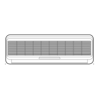
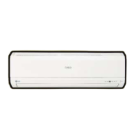
Why LG LS-L1210CL Air Conditioner is not operating with the remote controller?
- CCassie CabreraAug 6, 2025
The LG Air Conditioner might not be operating with the remote controller due to several reasons: * The remote controller itself may be the cause. Check the contact of the CN-DISP connector. * If the mark is displayed on the LCD screen, replace the battery. * Other parts besides the remote controller could be the issue. In this case, check the DISP PWB Assembly and ensure the voltage between CN DISP is DC +5V. * Also, inspect the connecting circuit between the remote controller MICOM (No. (30)) - R17(2?) - IR LED - Q1 - R16(2.2K?).