D
Danielle LeonAug 2, 2025
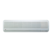
Why is the current low in my LG LS-M3061BL Air Conditioner?
- CChristina LeeAug 2, 2025
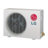
If your LG Air Conditioner exhibits low current due to a defective compressor or a defective 4-way reverse valve, a technician will need to diagnose and address the faulty component.