31
General Refrigerant Piping System Information
'XHWRRXUSROLF\RIFRQWLQXRXVSURGXFWLQQRYDWLRQVRPHVSHFL¿FDWLRQVPD\FKDQJHZLWKRXWQRWL¿FDWLRQ
©
/*(OHFWURQLFV86$,QF(QJOHZRRG&OLIIV1-$OOULJKWVUHVHUYHG³/*´LVDUHJLVWHUHGWUDGHPDUNRI/*&RUS
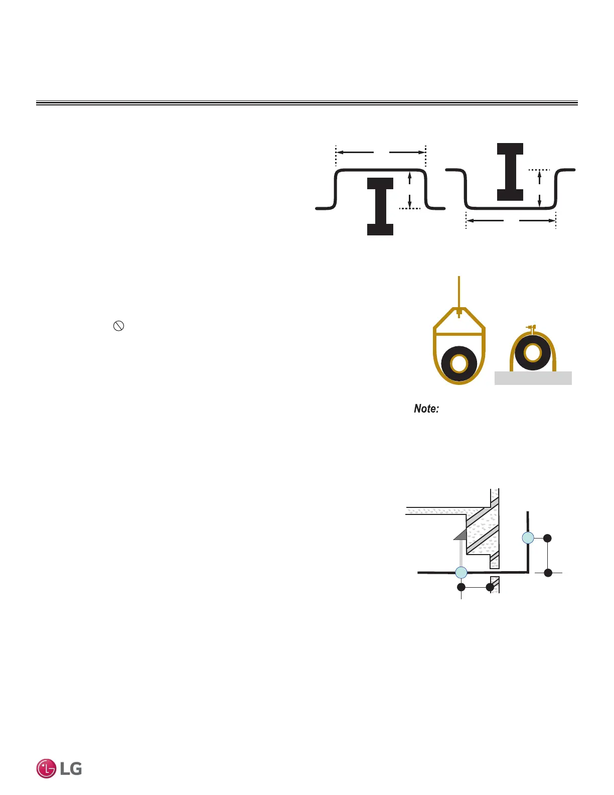
Figure 32: Installing Piping Above and Below an Obstacle.
Obstacles
When an obstacle, such as an I-beam or concrete T, is in the path
of the planned refrigerant pipe run, it is best practice to route the
pipe over the obstacle. If adequate space is not available to route
the insulated pipe over the obstacle, then route the pipe under the
obstacle. In either case, it is imperative the length of the horizontal
section of pipe above or below the obstacle be a minimum of three
(3) times the longest vertical rise (or fall) at either end of the
segment.
MINIMUM
Above an obstacle
MINIMUM
Below an obstacle
3X
X
3X
X
Pipe Supports
A properly installed pipe system must be adequately supported to avoid pipe sagging. Sag-
ging pipes become oil traps that lead to equipment malfunction.
Pipe supports must
never touch the pipe wall; supports must be installed outside
(around) the primary pipe insulation jacket. Insulate the pipe first because pipe supports
must be installed outside (around) the primary pipe insulation jacket. Clevis hangers must
be used with shields between the hangers and insulation. Field provided pipe supports must
be designed to meet local codes. If allowed by code, use fiber straps or split-ring hangers
suspended from the ceiling on all-thread rods (fiber straps or split ring hangers can be used
as long as they do not compress the pipe insulation). Place a second layer of insulation over
the pipe insulation jacket to prevent chafing and compression of the primary insulation within
the confines of the support pipe clamp.
A properly installed pipe system will have sufficient supports to avoid pipes from sagging
during the life of the system. As necessary, place supports closer for segments where poten-
tial sagging could occur. Maximum spacing of pipe supports must meet local codes. If local
codes do not specify pipe support spacing, pipe must be supported:
• Maximum of five (5) feet on center for straight segments of pipe up to 3/4 inches outside
diameter size.
• Maximum of six (6) feet on center for pipe up to one (1) inch outside diameter size.
• Maximum of eight (8) feet on center for pipe up to two (2) inches outside diameter size.
Wherever the pipe changes direction, place a hanger within twelve (12) inches on one side
and within twelve (12) to nineteen (19) inches of the bend on the other side.
Figure 33: Pipe Hanger Details.
Use a 4" + long sheet curved sheet metal
saddles between hanger bracket and insula-
tion to promote linear expansion/contraction.
Figure 34: Typical Pipe Support Location—
Change in Pipe Direction.
Max. 12"
~ 12" – 19"
REFRIGERANT SYSTEM ENGINEERING
 Loading...