36
MULTI F / MULTI F MAX Outdoor Unit Installation Manual
Due to our policy of continuous product innovation, some specifications may change without notification.
©LG Electronics U.S.A., Inc., Englewood Cliffs, NJ. All rights reserved. “LG” is a registered trademark of LG Corp.
MULTI
F
MAX
MULTI
F
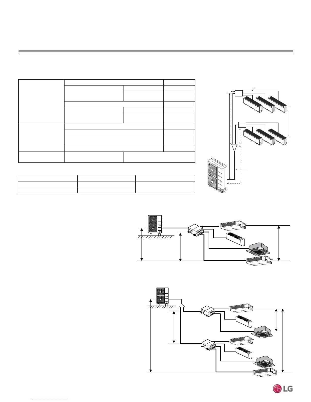
7KHIROORZLQJDUHH[DPSOHVRIPDQXDOSLSHVL]HFDOFXODWLRQV'HVLJQHUVDUHKLJKO\HQFRXUDJHGWRXVH/$76IRU0XOWL)V\VWHPV
Example: LMU540HV outdoor unit with seven (7)
indoor units, and two (2) branch distribution units
connected.
ODU: Outdoor Unit.
IDU: Indoor Unit.
BD: Branch Distribution Unit(s).
Ȉ$0DLQ3LSH
Ȉ%%UDQFK3LSH%UDQFK'LVWULEXWLRQ8QLW>V@WR,QGRRU8QLW>V@
B
A
h2 ≤ 49.2 feet
A
h3 ≤ 32.8 feet
h4 ≤ 49.2 feet
h1 ≤ 98.4 feet
BDU Y-Branch
BDU
IDU
A
ODU
IDU
IDU
IDU
IDU
IDU
IDU
B
B
B
B
B
B
Pipe Length
(ELF = Equivalent
Length of pipe in
Feet)
7RWDOSLSLQJOHQJWKȉ$ȉ% IHHW
Main pipe (Outdoor Unit to
Branch Distribution Units:
ȉ$
Minimum 9.8 feet
Maximum IHHW
7RWDOEUDQFKSLSLQJOHQJWKȉ% IHHW
Branch pipe (Branch
Distribution Units to Indoor
Units: B)
Minimum 10 feet
Maximum IHHW
Elevation Differential
(All Elevation
Limitations are
Measured in Actual
Feet)
If outdoor unit is above or below indoor unit (h1) IHHW
Between the farthest two indoor units (h2) IHHW
Between branch distribution unit and farthest
connected indoor unit(s) (h3)
IHHW
Between branch distribution units (h4) IHHW
Max. Combination of
IDUs
LMU480HV = 65,000 LMU540HV = 73,000
Piping Main Pipe A (inch) Branch Pipe B
Liquid Ø3/8
Depends on the size
of the indoor unit piping
Gas Ø3/4
Example: LMU540HV outdoor unit with four (4)
indoor units, and one (1) branch distribution unit
connected.
ODU: Outdoor Unit.
IDU: Indoor Unit.
BDU: Branch Distribution Unit.
A: Main Pipe.
%%UDQFK3LSH%UDQFK'LVWULEXWLRQ8QLWWR,QGRRU8QLW>V@
A
h2 ≤ 49.2 feet
h3 ≤ 32.8 feet
h1 ≤ 98.4 feet
BDU
ODU
IDU
IDU
IDU
IDU
B
B
B
B
Multi F MAX System Example with One Branch Distribution Unit
Multi F MAX System Example with Two Branch Distribution Units
Multi F MAX Outdoor Unit Piping Length and Elevation Limitations
Table 22: Multi F MAX Refrigerant Piping System Limitations.
h1
C
Branch Pipe
Main Pipe
BD Unit
BD Unit
A
B
h2
Figure 42: Multi F MAX Refrigerant Piping
System Limitations.
Table 23: Multi F MAX Piping Sizes.
REFRIGERANT PIPING CONNECTIONS
 Loading...

