51
Installation Manual
Due to our policy of continuous product innovation, some specifications may change without notification.
©LG Electronics U.S.A., Inc., Englewood Cliffs, NJ. All rights reserved. “LG” is a registered trademark of LG Corp.
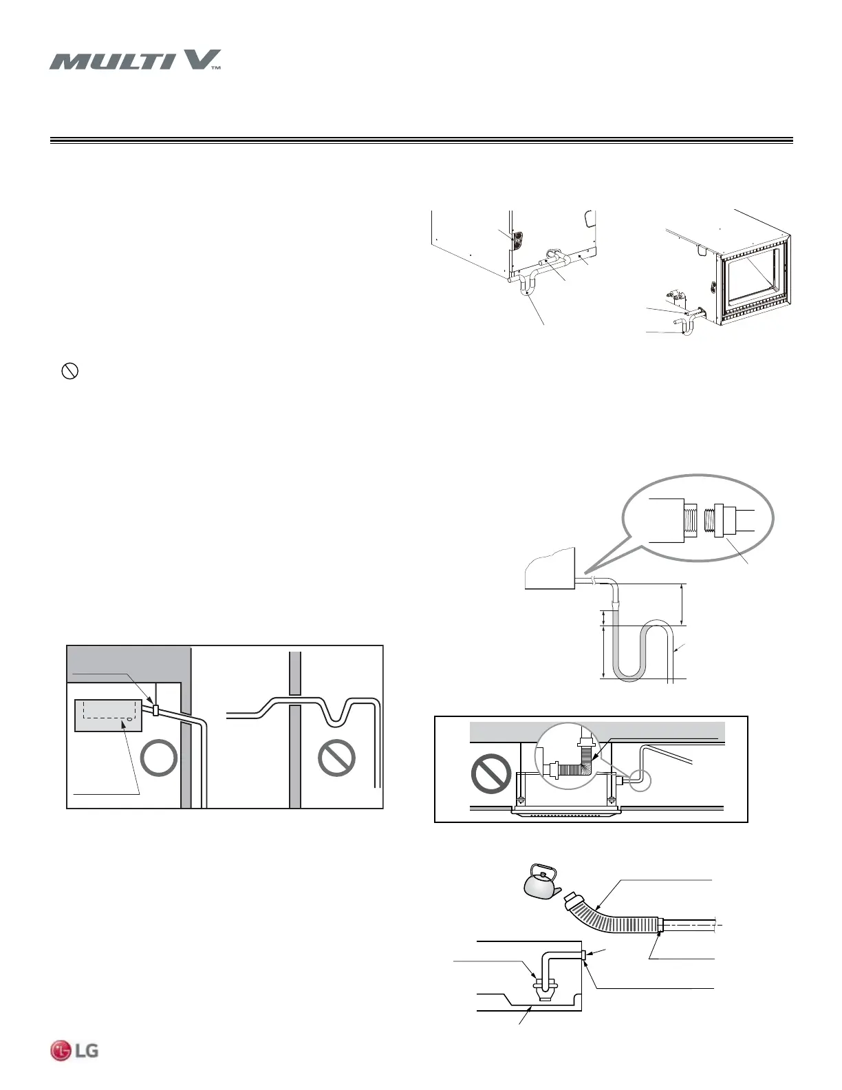
CONDENSATE PIPING
Vertical/Horizontal AHU Condensation Drain Pipe Installation
• Drain piping must slope down or ow may reverse back to unit.
• During drain piping connection, be careful not to exert extra force on
the drain port on the indoor unit.
• Refer to Table 20 for drain pipe sizing.
• Use polyvinyl chloride pipe.
1. Refer to Figure 48 and plan the drain pipe routing so that the pipe
will slope downward from the indoor unit to its end drain loca-
tion.
2. Connect the provided flexible drain pipe to the main drain pipe.
3. Pour water into the flexible pipe as shown in Figure 50 to test for
leaks. Repair leaks if necessary.
4. Route the flexible drain pipe to the indoor unit and connect the
flexible drain pipe to the drain port of the indoor unit.
5. Install field supplied polyethylene foam insulation 5/16 inch thick
or greater on the flexible drain pipe and position snugly against
indoor unit.
Figure 46: Vertical / Horizontal Air Handler Unit Drain Piping System.
Figure 47: Vertical / Horizontal Air Handler Unit U-Trap Specications.
U-Trap
B
C
A ≥
2-3/4 inch
B ≥ 2C
C ≥ 2 x SP
SP = External Pressure
(in. WG)
Ex) External Pressure
= 0.39 in. WG
A ≥ 2-3/4 inches
B ≥ 1-9/16 inches
C ≥ 25/32 inches
A
Applied U-Trap Dimensions
• Install the U-Trap to prevent leaks
caused by blocking the intake air filter.
3/4 inch
connector
Vertical/Horizontal Air Handler Unit (AHU) Drain Information
Note:
Install a eld-supplied external condensate pan underneath the entire
vertical air handling unit to avoid damage due to condensate overow.
Vertical / Horizontal Air Handler units have a gravity drain.
• Avoid blocking lter access panel when connecting drain lines.
• An additional external condensate line should run from the unit into
the pan.
• The entire condensate line should be drained from the external
condensate pan.
• Point the drain hose downward for easy drain ow.
•
Do not use pipe joint connection or PVC/CPVC for the unit drain
line connection. Use Teon® tape.
Maintenance
drain port
Upward
routing
not allowed
Pipe clamp
Indoor unit
Figure 48: Drain Piping Slope.
Flexible drain hose
Figure 49: Do Not Sharply Bend Drain Pipe.
Pour water to
test for proper
drainage and
no leaks
Drain Pump
Drain pan
Flexible drain hose
Main drain pipe
Glue the joint
Drain
port
Drain hose clip (provided)
Figure 50: Testing the Drain Pipe.
Upflow Drain Horizontal-left Drain
Horizontal-left
Drain Knockout
Air filter cover
Main drain along with suitable trap.
( Field supplied trap with sufficient
depth can be used. P-traps of standard
size are not sufficient. Refer the figure
for recommended condensate trap.)
Supplementary drain
with proper trap. (field
supplied kit can be used)
 Loading...