52
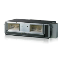
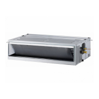
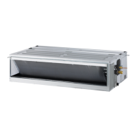
Multi V Ducted Indoor Units
Due to our policy of continuous product innovation, some specifications may change without notification.
©LG Electronics U.S.A., Inc., Englewood Cliffs, NJ. All rights reserved. “LG” is a registered trademark of LG Corp.
• All power wiring and communication cable installation must be performed by authorized service providers working in accordance with
local, state, and National Electrical Code (NEC) regulations related to electrical equipment and wiring, and following the instructions in this
manual. Failure to do so will lead to electric shock and bodily injury or death.
• Be sure that main power to the unit is completely off before proceeding. Follow all safety and warning information outlined at the beginning
of this manual. Failure to do so will cause electric shock and bodily injury.
• Familiarize yourself with the location of the circuit breaker. Be sure that a circuit breaker or some other emergency power cutoff device is in
place before any power wiring is done to the system. Failure to do so will cause bodily injury or death.
• Never touch any power lines or live cables before all power is cutoff to the system. To do so, will cause bodily injury or death.
• Undersized wiring will lead to unacceptable voltage at the unit and will cause a fire, which will cause bodily injury or death.
• Properly ground all outdoor units and indoor units. Ground wiring must always be installed by a qualified technician. Ground wiring is
required to prevent accidental electrical shock during current leakage, which will cause bodily injury or death.
• Install appropriately sized breakers / fuses / overcurrent protection switches and wiring in accordance with local, state, and NEC regulations
related to electrical equipment and wiring, and following the instructions in this manual. Generated overcurrent could include some amount
of direct current. Using an oversized breaker or fuse will result in electric shock, physical injury or death.
• Do not connect ground wire to refrigerant, gas, or water piping; to lightning rods; to telephone ground wiring; or to the building plumb-
ing system. Failure to properly provide a NEC-approved earth ground can result in electric shock, physical injury or death.
• The information contained in this manual is intended for use by a trained electrician familiar with applicable local codes and the U.S. Na-
tional Electric Code (NEC), and who is equipped with the proper tools and test instruments. Failure to carefully read and follow all instruc-
tions in this manual can result in equipment malfunction or property damage.
• Consider ambient conditions (temperature, direct sunlight, inclement weather, etc.) when selecting, installing, and connecting the power
wiring.
• Properly ground all outdoor units and indoor units. Ground wiring must always be installed by a qualified technician. Improperly ground wire
can cause communication problems from electrical noise, and motor current leakage.
• If there is a possibility of reversed phase, phase loss, momentary blackout, or the power goes on and off while the system is operating, in-
stall a field-supplied phase loss protection circuit. If the system operates in reversed phase, etc., it will damage the compressors and other
components.
• Install appropriately sized breakers / fuses / overcurrent protection switches and wiring in accordance with local, state, and NEC regulations
related to electrical equipment and wiring, and following the instructions in this manual. Generated overcurrent will include some amount of
direct current. Using an oversized breaker or fuse will result in equipment malfunction and property damage.
•
Do not connect ground wire to refrigerant, gas, or water piping; to lightning rods; to telephone ground wiring; or to the building plumb-
ing system. Failure to properly provide a NEC-approved earth ground can result in property damage and equipment malfunction.
General Information / Separating Wiring and Cables
WIRING
Capacity of Power Supply Wiring (current) Minimum Required Distance
1,2
100V or more
10A 12 inches
50A 20 inches
100A 40 inches
Exceeding 100A 60 inches
1
The gures above are based on parallel lengths up to 328 feet long. For lengths in excess of 328 feet, the distances will have to be recalculated in
direct proportion to the additional line lengths involved.
2
If the power supply waveform continues to exhibit some distortion, the space between the power wiring and communication cable must be in-
creased.
Table 21: Power Wire and Communications Cable Minimum Required Separation Allowable Distances.
Separating Power Wiring and Communication Cables
• Avoid running the power wiring and communication cable alongside each other; there is a strong likelihood of operation malfunction
due to electrostatic and electromagnetic interference. Do not run both in the same conduit.
• If running the power wiring and communication cable alongside each other cannot be avoided, see the table below for minimum required
distances.
• Do not secure the power wiring and communication cables together. It will result in equipment malfunction.
• Do not run the power wiring and the communication cable in the same conduit. It will result in equipment malfunction.
 Loading...