53
Installation Manual
Due to our policy of continuous product innovation, some specifications may change without notification.
©LG Electronics U.S.A., Inc., Englewood Cliffs, NJ. All rights reserved. “LG” is a registered trademark of LG Corp.
Terminal Connections
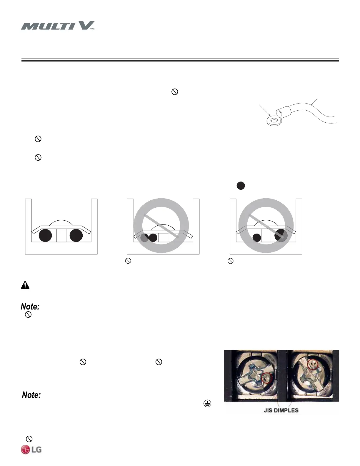
LG uses a “JIS” type of screw for all terminals; use a JIS screwdriver to tighten and
loosen these screws and avoid damaging the terminal. Do not overtighten the
connections — overtightening will damage the terminals — but firmly and securely at-
tach the wiring in a way to prevent external forces from being imparted to the terminal
block.
• The terminals labeled “GND” are NOT ground terminals. The terminals labeled
ARE ground terminals.
• Polarity matters. Always connect “A” to “A” and “B” to “B.”
• Always create a wiring diagram that contains the exact sequence in which all the indoor units (and heat recovery units) are wired in relation
to the outdoor unit.
• Do not include splices or wire nuts in the communication cable.
Figure 51: JIS Screws.
• Never apply line voltage power to the communications cable terminal block. If contact is made, the PCBs will be damaged.
• Always include some allowance in the wiring length when terminating. Firmly attach the wiring or cable, but provide some slack to facilitate
removing the electrical panels while servicing, and to prevent external forces from damaging the terminal block.
:Copper Wire
Terminate multiple power wires of
the same gauge to both sides.
Do not terminate two wires on
one side.
Do not terminate different gauge
wires to a terminal block.
Power Wiring / Communication Cable Connections
Best practice dictates using solderless ring or fork terminals at all power wiring and communica-
tion cable terminations. Use copper bearing ring or fork terminals; do not use galvanized or
nickle plate over steel. Use appropriate crimping tool to attach the ring or fork terminals at all
power wiring and control cable terminations. To install:
• Firmly attach the wire; secure in a way to prevent external forces from being imparted to the
terminal block.
• Use an appropriately sized JIS screwdriver for tightening the terminals.
• Do not overtighten the connections; overtightening will damage the terminals.
If ring terminals or fork terminals are not available, then:
•
Do not terminate different gauge wires to the power terminal block. (Slack in the wiring will generate heat.)
• When terminating wires of the same thickness, follow the instructions demonstrated in the gures below.
If power wires are not properly terminated and rmly attached, there is risk of re, electric shock, and physical injury or death.
Ring Terminal
Figure 52: Close up of a Typical Ring
Terminal.
Figure 53: Proper and Improper Power Wiring Connections.
WIRING
Power Wiring / Communication Cable Connections
 Loading...