This document is an installation manual for LG PV Solar Modules, specifically covering N-TYPE and P-TYPE models. It provides comprehensive instructions for the safe and proper installation, operation, and maintenance of these solar modules.
Function Description
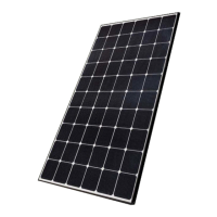
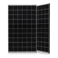
The LG PV Solar Modules are designed to convert sunlight into electrical energy. They are intended for outdoor use in solar power systems. The manual details the necessary steps for electrical and mechanical installation, ensuring the modules function efficiently and safely within a solar energy system. It also covers guidelines for transporting, storing, and disposing of the modules.
Important Technical Specifications
Module Types:
- N-TYPE MODELS: LGXXXN1C(W,K)-A5, LGXXXN2C(W,K)-A5
- P-TYPE MODELS: LGXXXS1C(W)-A5, LGXXXS2W-A5
Electrical Properties (P-TYPE, at Standard Test Condition: Irradiance 1000W/m², Cell temp. 25℃, 1.5AM):
- Power Tolerance: 0~3%
- Max. Series Fuse Rating: 20A for all listed P-TYPE models.
- Max. System Voltage: 1000V for 60-cell models (LGXXXS1C(W)-A5 series), and *1000/1500V for 72-cell models (LGXXXS2W-A5 series). Note: The Max. System Voltage of the 72-cell (LGXXXS2W-A5) for CANADA is 1000V.
- Bypass Diodes: Factory-installed, 25A (IF (AV)), 0.6V (VF (max)), 50V (VRRM), 200°C (Tj (max)), 2.0°C/W (RTH).
- Connectors: MC4/JM601A.
- MC4: Cable Cross Section 4mm² or 12AWG, ØA (Cable outer diameter) 5.5~9mm, Rated current 30A, Rated voltage 1500 V DC (UL).
- PV-JM601A: Cable Cross Section 4mm² or 12AWG, ØA (Cable outer diameter) 5.5~9mm, Rated current 20A, Rated voltage 1500 V DC (UL).
- MC4 formal name: PV-KST4 / 6II-UR, PV-KBT4 / 6II-UR.
- PV-JM601A formal name: PV-KST4 / 6II-UR, PV-KBT4 / 6II-UR.
- Plus (+) Connector: Female MC4 coupler (PV-KBT4/6II-UR).
- Negative (-) Connector: Male MC4 coupler (PV-KST4/6II-UR).
- A safety locking clip (MC PV-SSH4) may be required per article 690 of NEC 2008.
Mechanical Properties (P-TYPE):
- Dimensions (Length x Width x Height):
- 60-cell models (LGXXXS1C(W)-A5): 1686 mm x 1016 mm x 40 mm (66.4 in x 40.0 in x 1.6 in).
- 72-cell models (LGXXXS2W-A5): 2024 mm x 1024 mm x 40 mm (79.7 in x 40.3 in x 1.6 in).
- Weight:
- 60-cell models: 18.0 kg (39.7 lbs).
- 72-cell models: 21.7 kg (47.8 lbs).
- Design Strength (Basic Load):
- 60-cell Modules: 75 lb/ft².
- 72-cell Modules: 60 lb/ft².
- Mounting Distance (from module edge to mounting hole center):
- 60-cell: 200mm (7.9in) or 300mm (11.8in).
- 72-cell: 300mm (11.8in).
- Recommended Standoff Height: Minimum 100mm (clearance between solar module frames and structures).
- Fire Resistance: Class C after ANSI/UL790 Edition 2004, when installed on a fire-resistant roof covering. A slope less than 5in/ft is required to maintain a fire class rating.
- Frame: The solar module is Intertek listed for use only when its factory frame is fully intact. Creating additional mounting holes may damage the module and reduce frame strength.
- Gap between module frames: Recommended 6mm to avoid tension from thermal expansion.
Operating Conditions:
- Maximum Operating Temperature: +90°C (194°F).
- Minimum Operating Temperature: -40°C (-40°F).
- Excluded Operating Environments: Locations where modules could come into direct contact with salt water or ammonia.
Usage Features
Installation:
- Qualified Installer: Installation and maintenance must be performed by a qualified and authorized installer.
- Safety First: Emphasizes reading the manual carefully, working in dry conditions with dry tools, and using appropriate safety gear.
- Electrical Connections: Modules can be connected in series and/or parallel. Polarity must be matched. Only same type of modules should be used in a combined source circuit. Connectors of each module should be the same product when installing in series or parallel.
- Earth Grounding: All work must conform to Federal, State, and local codes. Grounding should be performed by an authorized installer. Specific grounding hardware (M4 stainless steel bolt, nut, spring washer, flat washers, cup washer, star washer, 12 AWG Cu wires) is recommended. Torque for screws and nuts: 4~5 N-m.
- Mounting Methods:
- Frame Bolt Holes: Secure using factory mounting holes. Four M8 (5/16inch) stainless steel bolts, four nuts, four spring washers, and eight flat washers are recommended per module. Modules should be fastened at a minimum of 4 points on two opposite sides. Torque: 8~12 N·m.
- Clamps: Modules can be fastened to a support using clamps on both long and short edges.
- Mounting Rails: Use corrosion-resistant material (aluminum, stainless steel). Recommended rails are more than 40x40mm.
- Orientation: Select appropriate orientation to maximize sunlight exposure.
- Snow Areas: In heavy snow areas, appropriate countermeasures are recommended to prevent damage to the lower side frame from slipping snow. Corrosion-resistant material (UL 1703 or UL2703 standard) should be used for supporting parts.
- NEXTracker Installation: For Fig. 7 bolting type, follow NEXTracker's recommended applied torque and materials.
Safety Precautions:
- Danger: Do not contact electrically active parts without safety gear. Do not use or install if the module is broken or torn. Do not reconnect or repair junction box cables. Do not bend junction box cables excessively (bending radius > 4 times cable diameter).
- Warning: Do not handle wet panels without protection equipment. Damaged modules must be treated with safety protection equipment by authorized experts.
- Caution: Use proper equipment, connectors, wires, and buttresses. Avoid installation during rain, heavy wind, or snowy days. Do not create holes in the frame or glass.
- General: Do not touch glass or frame after installation. Keep heavy objects off modules. Do not stand or step on modules. Do not drop modules. Do not scratch the frame coating. Do not artificially concentrate sunlight. Do not apply shock to the junction box or pull cables. Do not remove labels.
Maintenance Features
After Installation:
- Connector Check: Ensure connectors are tightly plugged and wiring works properly.
- Periodic Inspection: Inspect panels for damage to front glass, back sheet, frame, junction box, or external electrical connections.
- Electrical Connections Check: Look for loose connections and corrosion.
- Cleaning:
- Front glass can be cleaned with water, ethanol, or a conventional glass cleanser with a micro-fiber cloth to remove dust, dirt, or other deposits.
- Avoid aggressive, abrasive, or alkali chemicals (including ammonia-based solutions) for cleaning.
- Foreign material on the frame surface can be cleaned with a wet sponge or cloth and dried with a clean chamois.
- Wiring Work: Perform wiring work by connecting connectors and wires away from the roof or ground.
- Dirt Buildup: Avoid low tilt angles that may cause dirt buildup on the glass against the frame edge, as this can shade active solar cells and impair electrical performance.
Transporting and Storage:
- Banding: Do not loosen banding during transport to prevent damage from shaking.
- Stacking: Do not stack more than one pallet high (maximum two pallets) to avoid stress and product damage.
Disposal:
- Contact LG Electronics for queries related to the disposal or recycling of solar modules.
Warranty:
- The LG Electronics' (LGE) Limited Warranty for solar modules is contingent upon modules being mounted in accordance with the requirements described in the manual. Opening the junction box will void the warranty. Panels with suspected electrical problems should be returned to LG Electronics for inspection, repair, or replacement as per warranty conditions.