Do you have a question about the LG A005KEEN261 and is the answer not in the manual?
Manual contains important instructions for installation and maintenance of the LG Electronics ESS inverter.
Explains hazard symbols like DANGER, WARNING, CAUTION, NOTICE, INFO.
Installation by licensed electrician, compliance with local/national codes (NEC, ANSI/NFPA 70).
Inverter has no user-serviceable parts; refer servicing to authorized center.
Explains the LG Electronics ESS inverter's role in converting DC to AC and system design.
Details the function and configuration of PV modules in DC-coupled and AC-coupled systems.
Describes the Battery Pack's role in storing surplus energy for later use.
Explains the Rapid Shutdown Device (RSD) for PV system safety compliance.
Describes ATS, Meter functions, Grid voltage support, and configuration options.
Details mobile app usage and LG Electronics cloud connectivity.
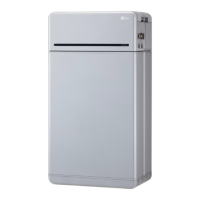
Identifies and describes the main external components of the inverter.
Details the information presented on the inverter's type label and specifications.
Explains the warnings and precautions indicated on the inverter's caution labels.
Provides detailed measurements and diagrams for the ESS inverters.
Identifies the terminals within the wiring box and required torques for connections.
Safety warnings for installation, including compliance with electrical codes and regulations.
Cautions regarding electrical connections, such as short-circuit current and fire risk.
Verifies shipping carton contents and inspects for any physical damage to the inverter.
Warns against opening the inverter as it contains no user-serviceable parts and voids warranty.
Specifies mounting on non-flammable base, vertical mounting, and required clearances for convection.
Covers mounting hardware, resonating surfaces, indoor/outdoor installation, and ambient temperature.
Illustrates required clearances and provides dimensions for the inverter mounting plate.
Steps for marking, drilling, and securing the mounting plate to a wood stud wall.
Guidance on lifting and securing the inverter to the mounted plate by two persons.
Warnings about hazardous voltages from PV arrays and protective measures.
Mandates licensed electrician installation and specific wire gauge/type for optimal efficiency.
Requires utility approval before connecting to the AC grid, and connection by qualified personnel.
Specifies supported AC voltage ranges and frequency limits for grid connection.
Illustrates allowed public grid configurations for 240 V and 208 V systems.
Illustrates allowed AC grid configurations like WYE and Stinger types.
Shows public grid configurations that are not permitted for connection.
Requires a dedicated circuit breaker for each inverter, with exceptions for sub-panels.
Details GEC installation, sizing per NEC, and termination in the wiring box.
Recommends external surge protection due to unique PV installation factors.
Ensures PV string voltage is under 450 V DC using manufacturer's V/Temp coefficient.
Advises keeping system wiring voltage losses to 1-2 percent for optimal efficiency.
General warnings about PV arrays, installation by electricians, and DC disconnect status.
Warns that exceeding max DC input voltage or opening the inverter voids the warranty.
Specifies maximum allowed wire size for PV and requires permanent mounting before wiring.
Ensures DC disconnect is in OFF position before removing the wiring box cover.
Steps for removing the wiring box cover using a hex screw driver and noting torque.
Details available conduit plug sizes (3/4" and 1/2") and the use of reducers.
Warns against enlarging conduit openings as it can damage the enclosure and void the warranty.
Illustrates the procedure for removing conduit plugs using a flat blade screwdriver.
Specifies watertight conduit fittings (NEMA 4, 4X, 6, 6X) and insulated types.
Routes wiring through conduit and allows for a 6" strain relief loop within the compartment.
Critical warnings about hazardous contact voltages, electric shock, and ungrounded DC conductors.
Cautions on polarity verification and connection, and info on wire size and driver type.
Connects PV array strings to PV Positive/Negative terminals and battery to Battery terminals.
Verifies correct wiring for the DC wiring board assembly and wire color conventions.
Emphasizes connecting to earth grounding first and the need for a ring terminal connector.
Steps to remove power, lockout the circuit breaker, and prevent accidental turn-on.
Details attaching a tag with information about who, why, and when the breaker was locked out.
Connects positive and negative leads to Battery Positive/Negative terminals and verifies wiring.
Notifies about fuse type (Littelfuse KLKD 600 V, 30 A) and how to change it.
Strips four wires of the battery pack communication cable and inserts them into the plug.
Matches cable connector names with the battery pack connectors for proper communication.
Connects power cables to ground, negative, and positive terminals, specifying cable type and length.
Connects communication cables to ground, ENABLE_High, RS485_High, and RS485_Low terminals.
Sequence for connecting power/communication cables and activating the disconnect switch and circuit breaker.
Warns against pushing switch ends, which could damage the product.
Identifies terminals for RS485, L1/L2 CTs, L1/L2 terminals, N terminal, and Ground.
Instructs to clamp CT to L1 CT around wire connected to ØL1 and L2 CT around wire to ØL2.
Illustrates energy meter connection to the inverter, power distribution box, and utility grid.
Shows an alternative energy meter connection with additional CT requirement.
Explains LED colors (Green, Red, Yellow) and their indications for power status and troubleshooting.
Explains LED indications for positive/negative power, voltage, and frequency status.
Strips energy meter cable wires and inserts them into the plug for inverter connection.
Matches energy meter connector names with the inverter's energy meter connections.
Safety warnings, installation by electrician, and wire size requirements for AC output.
Informs that the AC output (neutral) is not bonded to ground in the inverter.
Identifies L1, N, L2, and Ground terminals for AC output wiring assembly.
Mounts AC disconnect, installs conduit, and routes AC output wires through conduit.
Terminates Neutral, L1, and L2 wires to their respective terminals using specified torque.
Emphasizes checking neutral wire reliability for correct phase voltage detection and grid feed-in.
Steps for opening ATS cover, removing hole tapes, and installing conduit.
Routes AC wires through conduit, strips ends, and connects them to Inverter/Grid/Load terminals.
Connects the wire (GND) to the Grounding terminal, specifying wire gauge and torque.
Specifies compatible wiring gauge (10-4 AWG) and capacity based on NEC 2017.
Details RS485 interface for daisy-chaining inverters and communication port types.
Provides pin assignment for CAN and RS485 communication ports.
Details pin assignment for Ethernet communication ports (ETH TD+, TD-, RD+, RD-).
Provides pin assignment for RS485 communication ports (Energy meter and Battery).
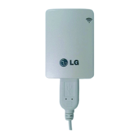
Steps for taking out the antenna, removing the cover, inserting, and tightening it.
Connects the installed antenna to the module for Wi-Fi functionality.
Instructions to download and install the LG EnerVu2 Professionals App from app stores.
Explains the main screen layout, displaying system and cloud connection status.
Requirements for Bluetooth connection: mobile device support, serial number check, and LG ESS account creation.
Steps for logging into the app and searching for the installed ESS via the LG ESS button.
Inputting the 4-digit date code found on the PCS device to connect to the system.
Displays the event screen after a successful connection, showing load, battery, and grid status.
Supports wired (Ethernet) and wireless (WLAN) connections for Enervu cloud, with wired connection prioritized.
Checking internet connection status via the [Network] -> [Network Info] menu.
Items configurable in Settings: Operation Mode (TOU), Backup SOC, Grid Type, and Grid Profile.
Caution on setting the grid profile correctly; contact grid operator for information.
Steps to create a new system and fill in system & home owner information via the app.
Warnings for installation, commissioning by licensed electrician, and circuit breaker status.
Explains the meaning of the five LEDs on the front of the inverter for operational status.
Details status indications for OPER LED (Normal, Sync, Night Mode) and troubleshooting.
Explains BAT LED status (fault, standby, low power) and COMM LED status (BLE, XBee, Gateway).
Explains INFO LED behavior for firmware upgrade, reset button actions, and image reception.
Details FAULT LED status for Arc Fault and Ground Fault occurrences.
Describes Arc reset, Arc self-test, and Gateway reset functions triggered by the internal button.
Steps to turn on the inverter, including breaker, battery disconnect, and DC disconnect.
Steps to turn off the inverter, including DC disconnect, battery breaker, and AC disconnect.
Warnings about hazardous voltage during repair and that the inverter has no user-serviceable parts.
Safety precautions for decommissioning, including disconnecting from grid and securing DC connections.
Recommends annual inspection by a technician or authorized professional.
Instructs to dispose of the product according to electronic waste regulations by qualified personnel.
Provides contact details for technical problems or questions with installation company or LG Electronics.
Explains how to find event messages and troubleshooting guides within the mobile app's Support section.
Details the ESS event guide screen, divided into Battery, PCS, and EMS categories.
Provides troubleshooting information by selecting the TS number in the Solutions tab.
Outlines the operation sequence for turning off/on switches and breakers for troubleshooting.
Lists open source software used, their licenses, and copyright information.
Provides URLs for obtaining details of the various open source licenses used.
Lists specifications for PV input voltage, current, MPPT, efficiency, and terminals.
Lists specifications for battery pack size, I/O power, voltage range, current, and DC disconnect.
Details AC output power, voltage range, current, frequency, and grid support compliance.
Lists specifications for off-grid output power, voltage, current, frequency, and crest factor.
Covers isolation level, converter type, efficiency, operating temperature, and altitude.
Details dimensions, weight, cooling, enclosure, installation type, and interface protocols.
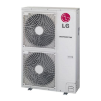
Lists available accessories like Rapid Shutdown Box, Energy Meter, and Auto-Transfer Switch.
Lists safety marks, general safety, software safety, grid, EMC, AFCI, and meter standards.
Details FCC ID, frequency range, and output power for the Wi-Fi module.
Details FCC ID, frequency range, and output power for the Bluetooth module.
Covers FCC compliance for Class B digital device, interference, and operation conditions.
States FCC limits for RF exposure and installation requirements for compliance.
Provides LG Electronics USA, Inc. trade name, address, and telephone number.
Covers Industry Canada compliance for license-exempt RSSs and operation conditions.
States IC limits for RF exposure and installation requirements for compliance.
Warns about high-power radars potentially causing interference or damage to LE-LAN devices.
Details RF exposure requirements and antenna gain limits for devices operating in 5 GHz bands.
Defines terms like AC, AFCI, AHJ, Anti-islanding protection, CEC, CSA, DC, EMC, ESS, FCC, GEC, GND, IEEE.
Defines terms like Initialization, ISC, MPP, NEC, Nominal power, PE, Photovoltaics, Power dissipation, PV cell.
Defines terms like RS485, Separate grid system, String, UL, VOC.
Details prerequisites and operating procedures for AC charging in islanded backup mode.
Diagram and table showing connection overview, terminals, AWG, and torque specifications.
Illustrates energy meter and ATS connection diagrams.