Do you have a question about the LG OM7560 and is the answer not in the manual?
Safety and handling instructions for servicing the unit, including pick-up care.
Guidelines for handling electrostatically sensitive devices (ESD) to prevent component damage.
Instructions for activating and using the hidden key mode for special functions.
Procedures for accessing and managing EEPROM data, including clearing and writing.
Steps for downloading firmware for Audio, CD, and EQ programs via USB.
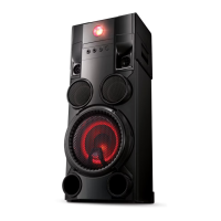
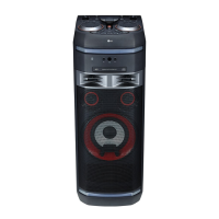
Technical specifications for the device's general, input, tuner, and amplifier features.
Step-by-step guide for disassembling the unit's cabinet and main chassis components.
Detailed diagrams showing the assembly of cabinet, main frame, mechanism, and accessories.
Troubleshooting guide for specific single-point failure issues with detailed steps.
Flowcharts for diagnosing and resolving common electrical problems in the unit.
Oscilloscope waveform examples for key test points to aid in troubleshooting.
Diagram illustrating the internal wiring connections between different modules and components.
High-level diagrams showing the functional blocks and signal flow within the system.
Detailed schematics of various circuits including SMPS, DSP, AMP, and I/O paths.
Table listing voltage measurements at IC inputs and capacitor locations for diagnosis.
Visual layouts of the physical PCB components for SMPS, Main, Top Front, and other boards.
Lists and diagrams showing the location of various parts of the deck mechanism.
Detailed exploded view diagram of the DM19AC deck mechanism for assembly reference.
| power consumption networked standby | 0.5 W |
|---|---|
| bus power supply (USB) | 5 V 0 500 mA |
| amplifier output power | 1, 000 W |
| frequency range | 2402 to 2480 MHz |
|---|---|
| output power | 10 dBm |
| minimum distance from body | 20 cm |
| dimensions | 330 mm x 815 mm x 302 mm |
|---|---|
| net weight | 16.8 kg |