4-5
5.
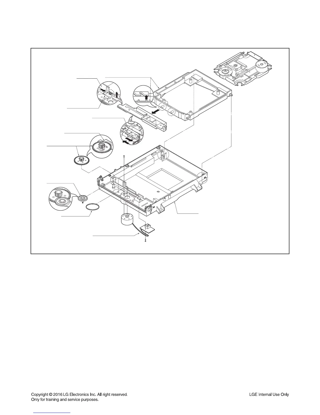
Frame Assembly Up/Down (Fig. 4-4)
Note
Put the Base Main face down(Bottom Side)
1) Release the screw(S4)
2) Unlock the Locking Tab(L3) in direction of arrow
and then lift up the Frame Assembly Up/Down
to separate it from the Base Main.
Note
• When reassembling move the Guide Up/Down
in direction of arrow(C) until it is positioned as
Fig.(C).
• When reassembling insert (A) portion of the
Frame Assembly Up/Down in the (B) portion of
the Guide Up/Down as Fig.(B)
6. Belt Loading(Fig. 4-4)
Note
Put the Base Main on original position(Top Side)
7. Gear pulley (Fig. 4-4)
1) Unlock the Locking Tab(L4) in direction of arrow(B) and
then separate the Gear Pulley from the Base Main.
8. Gear Loading (Fig. 4-4)
9. Guide Up/Down (Fig. 4-4)
1) Move the Guide Up/Down in direction of arrow(A) as
Fig.(A)
2) Push the Locking Tab(L5) down and then lift up the
Guide Up/Down to separate it from the Base Main.
Note
When reassembling place the Guide Up/Down as Fig.(C)
and move it in direction arrow(B) until it is locked by the
Locking Tab(L5). And confirm the Guide Up/Down as
Fig.(A)
10. PWB Assembly Loading(Fig. 4-4)
Note
Put the Base Main face down(Bottom Side)
1) Release 1 Screws(S5)
2) Unlock the Loading Motor (C2) from the Hook (H1) on
the Base Main.
3) Unlock 2 Locking Tabs(L6) and separate the PWB
Assembly Loading from the Base Main.
11. Base Main(Fig. 4-4)
GEAR PULLEY
BELT LOADING
PWB ASSEMBLY LOADING
BASE MAIN
(C2)
(S5)
Fig. 4-4
(L4)
GEAR LOADING
GUIDE UP/DOWN
(B)
(L5)
FIG. (A)
UP/DOWN FRAME ASSEMBLY
(A)
(A)
GUIDE UP/DOWN
BASE MAIN
(B)
(C)
GUIDE UP/DOWN
(A)
(B)