11
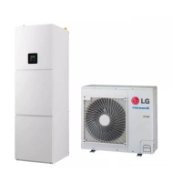
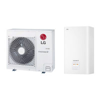
THERMA V Split Type
DHW Tank Integrated Unit
6. Piping diagrams
DHW Tank Integrated Unit
Symbol System Description
1
Cooling / Heating
Return flow
2 Heating Supply flow
3
Domestic Hot Water
Hot Water Outlet
4 Circulation flow Inlet
5 Cold Water Outleet
6
Outdoor Unit of Heat Pump
Gas pipe to ODU (based Cooling)
7 Liquid pipe from ODU (based Cooling)
8
Devices of Indoor Unit
Mg. Annode
9 Safety group (Pressure indicator, safety valve, automatic air vent)
TIC Temperature sensor
PIC Pressure indicator
M/F Magnetic Filter
3rd party accessory and Field installation
It is strongly recommended to install an additional filter on the
heating water circuit.
Basic installation
(IDU + ODU)
Fan
Coil
Unit
Underfloor
Heating
Radiator
Buffer
Ta nk
M
DHW
TANK
TIC
(Optional)
TIC
TIC
PIC
1
2
3
4
5
7
6
8
9
Water
Pump
Electric
Heater
Condenser
3Way
Valve
Flow
Switch
Field installation
Indoor Unit
1
1
1123
1
3
456
1 : Ball valve
2 : Pressure reducing valve
3 : Check valve
4 : Safety valve
5 : Expansion vessel
6 : Charging pipe
M/F
Magnetic
Filter
(Recommended)

 Loading...


