Do you have a question about the LG THERMA V Split and is the answer not in the manual?
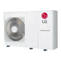
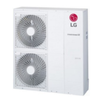
Explains the Therma V system as an Air to Water Heat Pump for heating, cooling, and DHW.
Illustrates the refrigerant cycle and main components of the Therma V system.
Details the physical layout and numbered components of the Therma V unit.
Provides configuration and features for System 1, focusing on generic floor heating/cooling.
Details System 2 configuration using indoor air temperature sensor for heating/cooling.
Describes System 3 for DHW exclusive operation using a heat exchanger in a DHW tank.
Outlines System 4 for DHW exclusive operation with separate heater control.
Details System 5 for Space heating/cooling and DHW using a 3Way valve.
Explains System 6 for FCU and floor heating, using a 2Way valve.
Describes System 7 for heating/cooling using indoor air sensor and dry contact.
Outlines System 8 for heating/cooling using indoor air sensor and thermostat.
Details System 9 for hot water at two temperatures using a Thermostatic valve.
Explains System 10 for floor heating with buffer tank and external pump.
Describes System 11 for remote operation via smartphone using Wi-Fi.
Outlines System 12 for DHW operation with solar heat as auxiliary.
Explains controller operation, display, buttons, and mode settings for the system.
Details the function of each DIP switch on the indoor unit PCB for system setup.
A comprehensive list to verify correct installation of piping, electrical, and unit placement.
Procedures for pilot operation, air purge, and checking system performance after installation.
| Refrigerant | R32 |
|---|---|
| Energy Efficiency | A+++ |
| Power Supply | 220-240V, 50Hz |
| Sound Power Level | Varies by model |
| Noise Level (Outdoor) | 45 dB - 55 dB |
| Indoor Unit Dimensions (WxHxD) | Varies by model |
| Outdoor Unit Dimensions (WxHxD) | Varies by model |
| Indoor Unit Weight | Varies by model |
| Outdoor Unit Weight | Varies by model |
| Air Flow (Indoor) | Varies by model |


