Installation check listConguration
System Design ApplicationsIntroduction
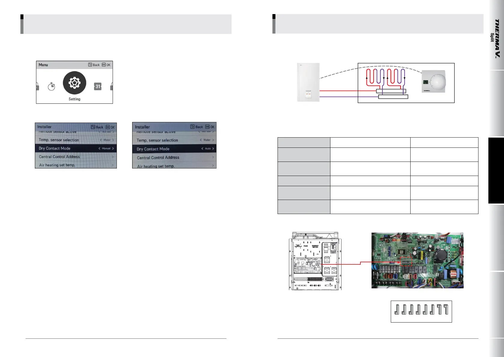
• Installer setting
Press ‘up’ for 3 sec
[DRY CONTACT]
Cable (1ea)
1. CN-POWER: Connector
2. CN-CC: Indoor PCB Connector
3. CN_DRY (L): DRY CONTROLLER Connector
4. CN_DRY (SIG): DRY CONTROLLER Connector
5. CN_DRY (ERROR CHECK): ERROR Check Display Connector
6. CN_DRY (OPER STATE): Operation Display Connector
1
2
6
5
4
3
• System diagram
Thermostat
IDU
Purpose: System installation for generic oor heating/cooling based on indoor air temperature sensor
Radiator/fan coil based heating and cooling
• Necessary conguration and feature
Dip s/w N/A
8 on
2/3 off
Remote controller
Use the default one attached to indoor
unit
No installation required
Leaving water tempera
-
ture
Set up by remote controller Single temperature
control Control of leaving water temperature
Thermostat Installation
Thermostat is an option and needs to
be purchased and installed separately.
Spec : 230V
Installer setting
Remote controller does not need to be
set up separately.
• Dip s/w Setting
OFF
ON
1 23 45678
Manual : 'off ' signal from drycontact Prod-
uct shall be 'off ' and locked.
'On' signal from dycontact, Prod-
uct shall be free from lock
Auto : 'off ' signal from drycontact Product
shall be 'off '.
'On' signal from dycontact, Product
shall run
032 033
_
COMPREHENSIVE APPLICATION AND INSTALLATION MANUAL
LG Electronics
8. System 8