Installation check listConguration
System Design ApplicationsIntroduction
System capable of space cooling, heating and providing DHW AWHP stands for "Air to Water Heat
Pump" and generally refers to Therma V system.
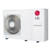
• Split model
Ref. Pipes
[Outdoor unit]
Water Pipes
[Floor heating]
[FCU] [Radiator]
[Hotwater]
Water Pipes
[Indoor unit]
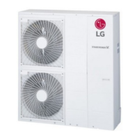
• Monobloc model
Ref. Pipes
[Outdoor unit]
Water Pipes
[Floor heating]
[FCU] [Radiator]
[Hotwater]
Water Pipes
• Application
Ref. Pipes
[Outdoor unit]
Water Pipes
[Floor heating]
[FCU] [Radiator]
[Hotwater]
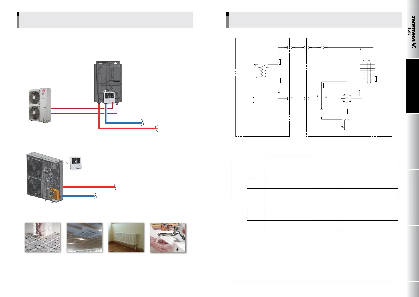
GAS SIDE
Service
Valve
(3 way)
EEV
Service
Valve
(3 way)
Indoor Unit
Plate Heat
Exchanger
Th2
Th3
Water. Out
Water. In
TH1
(Accessories)
TH6
TH4
Pressure
Sensor
Accumulator
Compressor
4 way
Valve
TH5
TH7
TH8
Outdoor Unit
Heat Exchanger
LIQUID SIDE
[Product : Split 3 ]
rd
Table of sensors
Category
Symbol Meaning
PCB Connector
Remarks
Indoor
Unit
Th1
Remote air temperature
sensor
CN_ROOM
- Optional accessory (being sold
separately)
- Not shown in diagram
Th2
Inlet evaporator temperature
sensor
CN_PIPE_IN
- Meaning is expressed based on
Cooling mode.
Th3
Outlet evaporator temperature
sensor
CN_PIPE_OUT
Outdoor
Unit
Th4
Compressor-suction pipe
temperature sensor
CN_SUCTION
Th5
Compressor-discharge pipe
temperature sensor
CN_DISCHA
Th6
Condenser temperature
sensor
CN_C_PIPE
- Description is expressed based on
Cooling mode.
Th7
Outdoor air temperature
sensor
CN_AIR
Th8
Condenser middle temperature
sensor
CN_MID
EEV Electronic Expansion Valve
CN_LEV1
Main components:
Heat exchanger (Refrigerant-Water)
Water pump
Electric heater / Strainer
Safety valve / Flow switch
Expansion tank / Remote controller
Main components:
Heat exchanger (Refrigerant-Water)
Water pump
Electric heater(Option)
Strainer/ Safety valve
Flow switch/ Expansion tank
Remote controller
008 009
_
COMPREHENSIVE APPLICATION AND INSTALLATION MANUAL
LG Electronics
1. Overview 2. Cycle Diagram