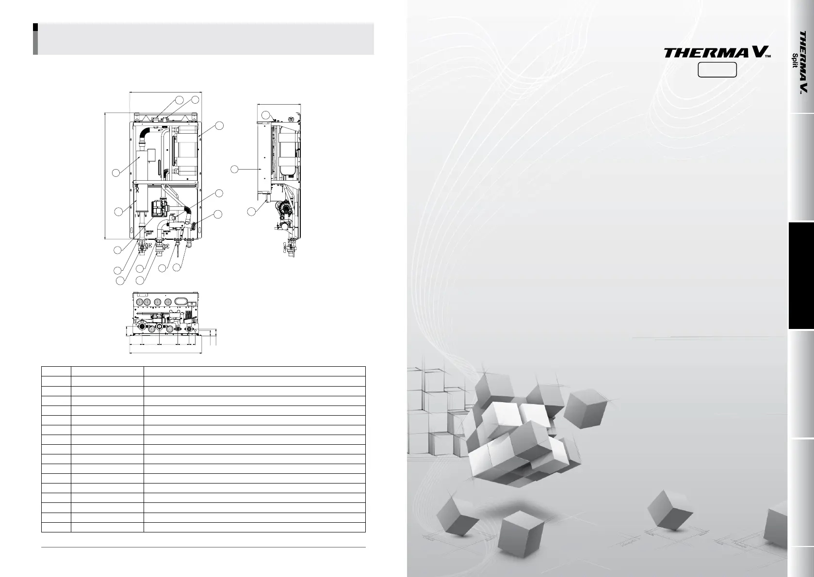
Water components
484
13
9
10
12
6
8
14
15
4
3
2
16
16
1
5
484
12311684.5
63.4
36.9
46.4
76 41
847.8
7
11
289.6
No Name Remark
1 Leaving Water Pipe Male PT 1 inch
2 Entering Water Pipe Male PT 1 inch
3 Refrigerant Pipe Ø9.52mm
4 Refrigerant Pipe Ø15.88mm
5 Water Pump Max Head 9.5 / 7 / 6 m
6 Safety Valve Open at water pressure 3 bar
7 Control Box PCB and terminal blocks
8 Thermal switch Cut-off power input to electric heater at 90 °C (manual return at 55 °C)
9 Flow Switch Minimum operation range at 15 LPM.
10 Plate Heat Exchanger Heat exchange between refrigerant and water
11 Pressure Gage Indicates circulating water pressure
12 Expansion Tank Absorbing Volume change of heated water
13 Air Vent Air purging when Charging water
14 Electric Heater Please refer to the below Page ‘Model name and related information’
15 Strainer Filtering and stacking particles inside circulating water
16 Shut-off valve To drain or to block water when pipe connecting
II.
System Design
Applications
1. System 1
2. System 2
3. System 3
4. System 4
5. System 5
6. System 6
7. System 7
8. System 8
9. System 9
10. System 10
11. System 11
12. System 12
Installation check listConguration
System Design ApplicationsIntroduction
Split
010
_
COMPREHENSIVE APPLICATION AND INSTALLATION MANUAL
3. Product Diagram