Do you have a question about the Liberty Pumps 237 and is the answer not in the manual?
Details risks of electric shock and necessary precautions during pump handling and maintenance.
Outlines fire hazards associated with pump operation and extension cord usage.
Covers general safety warnings regarding pump modification, qualified personnel, and environmental hazards.
Instructions for visually inspecting the pump and parts for damage upon arrival.
Guidelines for storing the pump properly to prevent damage and ensure longevity before installation.
Explanation of float switch types (automatic, manual, VMF) and their operation.
Steps for preparing an existing sump basin for pump installation, including cleaning and checks.
Details on excavating a new sump pit, recommended clearances, and bedding material.
Instructions for connecting the inlet and initial backfill procedures for new sump basins.
Guidance on proper backfilling of a new sump basin, emphasizing material type and compaction.
Procedures for placing the pump into the basin and ensuring correct mounting.
Instructions for making discharge pipe connections, including pipe size and check valve requirements.
Requirement to vent the basin in accordance with applicable plumbing codes.
Explanation of how to operate the pump manually using the piggyback switch.
Step-by-step guide for verifying and starting the pump system after installation.
Routine checks and actions for pump upkeep, including periodic operation and debris removal.
Guidance on identifying and resolving common pump operational issues and problems.
Details the terms and conditions of the limited warranty for Liberty Pumps products.
This document is an installation manual for Liberty Pumps' submersible sump pumps, specifically covering the 240-Series (1/4 hp Cast Iron), 230-Series (1/3 hp Poly/Aluminum), and 450-Series (1/2 hp Poly/Aluminum) models. These pumps are designed for drain (storm) water applications and are certified to CSA® and UL® standards.
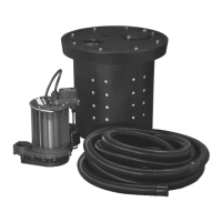
The Liberty Pumps submersible sump pumps are designed to remove drain (storm) water from a sump basin. They feature an integral anti-airlock hole in the volute housing, which allows trapped air to escape, enabling the pump to prime and start pumping effectively. A small spray of water from this hole is normal during pump operation. For added protection and in applications where loss of pump function could result in property damage, the manual suggests considering a back-up pump (e.g., Liberty Pumps SJ10 SumpJet) and an alarm (ALM-P1 or ALM-2), connected to a separate electrical circuit.
The manual details three main series of pumps with varying horsepower and construction materials:
All pumps are intended for use with fluid temperatures not exceeding 140°F (60°C). Operating the pump in higher temperatures can lead to overheating and failure. The discharge size for these pumps is 1-1/2" NPT threaded, and it should not be reduced to less than 1-1/4" as this can negatively impact pump flow and performance. Schedule 40 PVC pressure pipe is recommended for discharge lines, though flexible discharge hose kits can be used for temporary installations.
The sump basin diameter should be a minimum of 14" (10" for models 247, 237, and 457), with a larger diameter preferred for longer pump cycling and reduced switch cycling. The pit depth should be at least 12" above the surface on which the pump rests. A sump basin cover is required for safety and to prevent foreign objects from entering the basin. The pump should not be placed directly on earth, gravel, or debris; a hard, level bottom of bricks or concrete is recommended. Liberty Pumps offers "The Brick" (part #4445000) as a pre-molded stable platform to raise the pump 2-1/2" off the basin bottom, reducing jamming from rocks and debris.
For optimal air bleeding, a 1/8" hole drilled into the discharge pipe, just above the threaded connection to the pump discharge, is recommended.
The pumps come in various configurations regarding their activation method:
A check valve is required in the discharge line to prevent backflow of liquid after each pumping cycle. A gate valve should follow the check valve to allow for periodic cleaning or pump removal. The discharge line should be as short as possible with minimal turns to minimize friction head loss.
The manual emphasizes that no repair work should be carried out during the warranty period without prior factory approval to avoid voiding the warranty. Disassembly, other than by an authorized repair facility, automatically voids the warranty. For cord replacement, the new cord must be of the same length and type as originally installed.
| Model | 237 |
|---|---|
| Category | Water Pump |
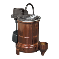
| Type | Submersible Sump Pump |
| Horsepower | 1/3 HP |
| Voltage | 115V |
| Discharge Size | 1-1/2" NPT |
| Cord Length | 10 ft |
| Switch Type | Vertical Mechanical |
| Maximum Head | 25 ft |
| Motor Housing Material | Cast Iron |
| Max Head | 25 ft |
| Construction | Cast Iron |
| Float Switch | Yes |
| Thermal Protection | Yes |
| Warranty | 3 years |
| Maximum Solid Size | 1/2 in |
| Maximum Flow Rate | 50 GPM |
| Max Flow | 50 GPM |