3
Tab.a--Ethyleneglycoltobeaddedtowater(%in
weight of total mixture)
Ethylene glycol
(% in weight)
0 10 20 30 40 50
Freezing tempera-
ture, ûC
(*)
0 --- 4 . 4 --- 9 . 9 --- 1 6 . 6 --- 2 5 . 2 --- 3 7 . 2
Mixture density at
20ûC
(*)
,kg/l
--- 1.017 1.033 1.048 1.064 1.080
(*) Values are for Shell antifreeze 402. For different brands, check
manufacturer’s data.
For the chiller int ernal water volume refer to Tab. 1. If the opti onal
buffer tank is installed on the machine, add the tank hydraulic
volume.
ALWAYS CHARGE THE HYDRAULIC CIRCUIT WITH THE RE-
QUIRED GLYCOL % NECESSARY FOR THE MINIMUM AMBI-
ENT TEMPERATURE AT THE INSTALLATION SITE. FAILING
TO COMPLY WITH THIS INSTRUCTION SHALL INVALIDATE
THE UNIT WARRANTY.
3.2 --- Connection of the safety valve dis-
charge
Safety valves are installed on the high pressure side of the refrig-
eration circuit(s): the discharge of these valves must be con-
veyed outside through a suitable pipe, having a diameter of at
least that of the valve outlet, without burdening the valve body.
Convey the discharge to areas where the jet cannot harm
people and the surrounding environment.
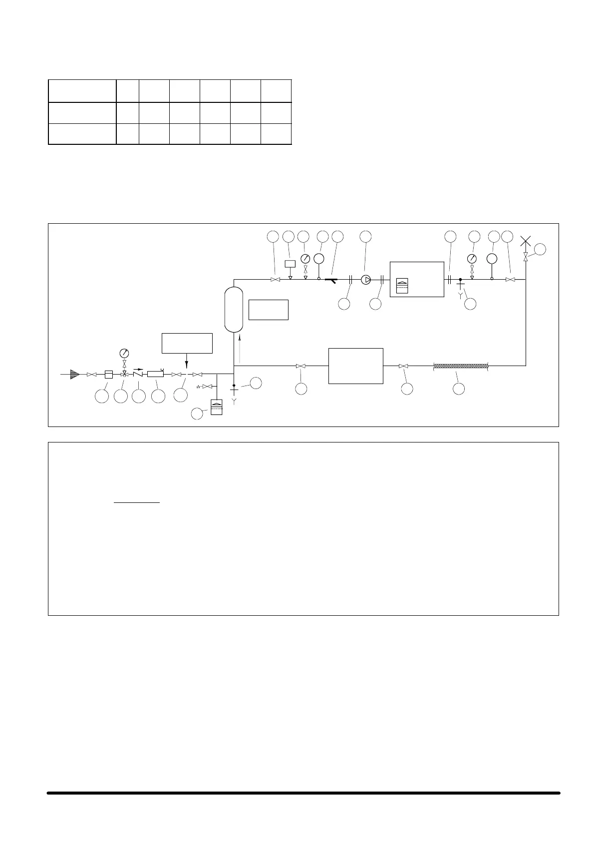
Fig. a --Ideal chilled water circuit
CHILLER
11
1 1327436
9
4
8
11
flow
12
10e
10d10c10b10a
T T
USER
5 5 9
disconnect af-
ter charge
Vpt
Ta n k
5
Fig. b -- Inertia tank sizing
The total optimum hydraulic volume of the system where the Matrix S chiller is installed can be calculated by the
following formula:
where:
--- V=minimum required total water volume expressed in litres
--- Rt=refrigeration capacity expressed in kW
--- Xd=differential band set on the control and expressed in degrees centigrade
Please note that the sum of the hydraulic volume of the Matrix S chiller (Vm) plus the volume of the hydraulic circuit
connected to it (Vpc) must be greater than, or equal to the minimum required total water volume (V). If this condi-
tion is not satisfied, it is necessary to install an inertia tank (Vpt, as indicated in the Fig. a) with a volume at least
equal to the following value: Vpt=V ---Vm ---Vpc
V =
43 x Rt
Xd
 Loading...