EasyManua.ls Logo

Lifebreath 150MAX User Manual

Lifebreath 150MAX
12 pages
To Next Page IconTo Next Page
Page #1 background imageLoading...
Page #1 background image
INSTALLATION
MANUAL
Models
150SP,
150MAX,
200STD,
200MAX
TOO0Z7
APPLICATION
WARNING!!!
It
is
always
important
to
assess
how
the
operation
of
any
Heat
Recovery
Ventilator
may
interact
with
vented
combustion
equipment
(i.e.,
Gas
Furnaces,
Oil
Furnaces,
Wood
Stoves,
etc.)
NEVER
install
a
Heat
Recovery
Ventilator
in
a
situation
where
its
normal
operation
(including
defrost
function),
lack
of
operation
or
partial
failure
may
result
in
the
backdrafting
or
improper
functioning
of
vented
combustion
equipment!
Do
Not
Attempt
Installing
Unit
Without
First
Reading
Entire
Manual

Other manuals for Lifebreath 150MAX

Question and Answer IconNeed help?

Do you have a question about the Lifebreath 150MAX and is the answer not in the manual?

Lifebreath 150MAX Specifications

General IconGeneral
BrandLifebreath
Model150MAX
CategoryFan
LanguageEnglish

Summary

Application Warning

Introduction

Tools Required

Engineering Data

Core

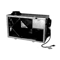
Material and classification of the HRV core.

Motor

Details on the high-efficiency PSC motor.

Filters

Information on washable air filters.

Blowers

Specs on centrifugal blowers and CFM delivery.

Connection Duct Sizes

Specifies the diameter of connection ducts.

Unit Dimensions

Provides length, width, height, and weight.

Mounting HRV

Describes mounting inserts and straps.

Case

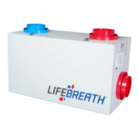
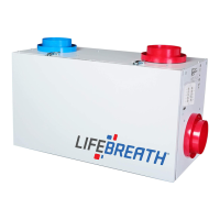
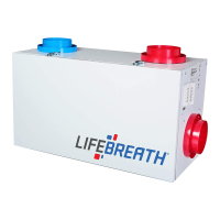
Details the construction of the unit's case.

Controls

Lists features like power switch, speed control, and defrost indicator.

Electric Defrost

Operation of Electric Defrost Models 150SP, 200STD

Details the automatic electric defrost cycle for 150SP and 200STD.

Damper Defrost

Operation of Damper Defrost Models 150MAX, 200MAX

Describes the electronic damper defrost cycle for 150MAX and 200MAX.

Location for Mounting

The Ductwork System

Outside Weatherhoods

Requirements for weatherhoods, including screens and placement.

Fresh Air Supply System

Stale Air Return System

Electrical Connections

Air Flow Balancing

Ducting from the Weatherhoods

Warm-Side Ducting - General

General guidelines for supply and return ducting.

Fresh Air Supply System

Installation Figure #6

Stale Air Return System

Electrical Connections

Air Flow Balancing

Other Installation Methods

Troubleshooting Your HRV

Related product manuals