6. Programmer's Reference DA2DVI-HDCP-Pro – User's Manual 22
6.4.7. Upload EDID Content to the Router
Description: EDID hex bytes can be written directly to the user programmable memory locations. The
sequence is the following:
Step 1.
Step 2. Router responds that it is ready to accept EDID bytes with (E_L_S)CrLf
Step 3. Send 1 block of EDID (1 block consist of 8 bytes of hex data represented in ASCII format) with
●<B1>●<B2>●<B3>●<B4> ●<B5>●<B6>●<B7>●<B8>}
Step 4. The router acknowledges with response (EL#<num>)
Step 5. Repeat steps 3 and 4 to send the remaining 31 blocks of EDID (32 altogether)
Step 6. After the last acknowledge, the router indicates that the EDID status changed by sending (E_S_C)
CrLf
Legend: <num> represents the sequential number of every 8 byte part of EDID. <num> is between 1 and 32.
<B1>..<B256> are the bytes of EDID.
Explanation: Full EDID uploaded to memory location U3.
Format Example
Command
→
{wl#U3}
Response (E_L_S)CrLf
←
(E_L_S) CrLf
Command ●<B1>●<B2>●<B3>●<B4>●<B5>●
<B6>●<B7> ●<B8>}
→
Response (EL#<num>)CrLf
←
(EL#1) CrLf
Command ●<B9>●<B10>●<B11>●<B12>●
<B13> ●<B14>●<B15>●<B16>}
→
Response (EL#<num>) CrLf
←
(EL#2) CrLf
… …
Command ●<B249>●<B250>●<B251>●
<B252>●<B253>●<B254>●<B255>●
<B256>}
→
Response (EL#<num>) CrLf
←
(EL#32) CrLf
Response (E_S_C) CrLf
←
(E_S_C) CrLf
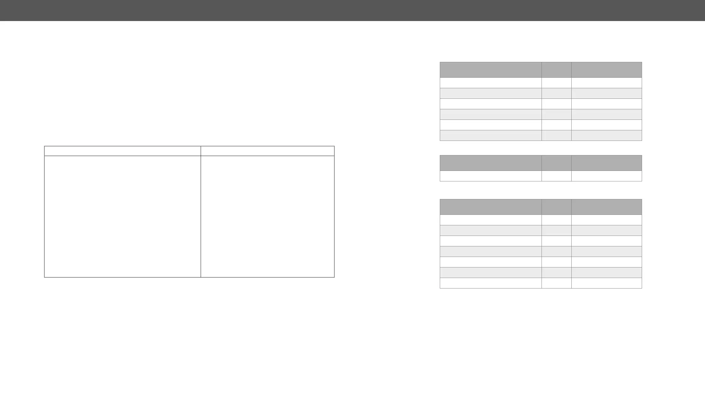
6.5. Commands - Quick Summary
Status Commands
System Commands
EDID Router Settings
Operation
See in
section
Command
View Product Type 6.2.1 {i}
View Serial Number 6.2.2 {S}
View Firmware Version 6.2.3 {F}
Compile Time 6.2.4 {CT}
View Installed Board 6.2.5 {IS}
View Board Information 6.2.6 {FC}
Operation
See in
section
Command
Restart the Device 6.3.1 {i}
Operation
See in
section
Command
Save EDID to User Memory 6.4.1 {<loc1>:<loc2>}
View Emulated EDID on Input 6.4.2 {VEDID}
6.4.3
View EDID Header 6.4.4
Delete EDID from Memory 6.4.5 {DE<loc>}
Download EDID Content 6.4.6
Upload EDID Content to the Router 6.4.7