3. Product Overview DA2DVI-HDCP-Pro – User's Manual 9
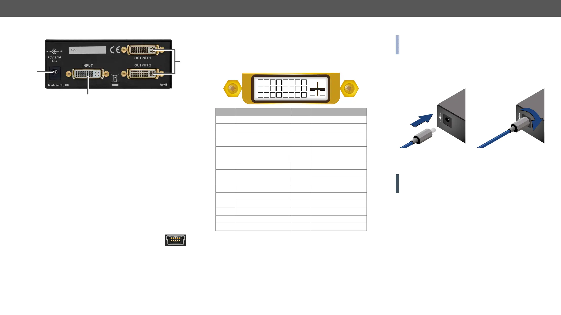
3.2. Rear View
3.3. Electrical Connections
3.3.1. USB Connector
The device provides a standard USB 2.0 mini B-type
control in Software Control – Lightware Device Controller section
and in Programmer's Reference section. For more information about
Firmware Upgrade section.
2
1
3
1
DC 5V in Connect the OUTPUT of the supplied +5V
power adaptor. The Power LED indicates the
proper supply voltage.
2
DVI Input Connect one Single-Link DVI cable (only
digital pins are connected internally) between
the DVI source and DA2DVI-HDCP-Pro.
3
DVI Outputs Connect one Single-Link DVI-D or DVI-I
cable (only digital pins are connected
internally) between DA2DVI-HDCP-Pro and
display device. The OUTPUT connector is
able to supply 500 mA current on pin 14 to
DVI-I
Connector section.
3.3.2. DVI-I Connector
DA2DVI-HDCP-Pro provides 29 pole „digital only” DVI-I Dual-Link
connectors (only digital pins are internally connected). This way, users
can plug in any DVI connector, but keep in mind that analog signals
(such as VGA or RGBHV) are not processed.
Always use high quality DVI cable for connecting sources and displays.
Pin Signal Pin Signal
1 TMDS Data2- 16 Hot Plug Detect
2 TMDS Data2+ 17 TMDS Data0-
3 TMDS Data2 Shield 18 TMDS Data0+
4 nc 19 TMDS Data0 Shield
5 nc 20 nc
6 DDC Clock 21 nc
7 DDC Data 22 TMDS Clock Shield
8 nc 23 TMDS Clock+
9 TMDS Data1- 24 TMDS Clock-
10 TMDS Data1+ C1 nc
11 TMDS Data1 Shield C2 nc
12 nc C3 nc
13 nc C4 nc
14 +5V Power C5 GND
15 GND (for +5V)
DVI Output
Monitor hotplug is detected on the OUTPUT ports (Monitor hotplug
LED lights green). After a hotplug event, the DA2DVI-HDCP-Pro tries to
read the EDID of the connected device.
Fiber Cable Powering
As a special feature, the device is able to supply 500 mA current on
DVI transmitters. Standard DVI outputs or VGA cards supply only 55
cable.
1 2 3 4 5 6 7 8
9 10 11 12 13 14 15 16
C1 C2
C4C3
C5
17 18 19 20 21 22 23 24
INFO: The device does not check if the connected sink (monitor,
projector or other equipment) supports hotplug or EDID signals but
outputs the input signal directly.
3.3.3. DC 5V Connection
The device has a locking DC connector to establish robust and safe
power connection. After plugging it in, turn the plug clockwise as you
can see in the picture below.
Locking DC Connector
Do not forget to turn the plug clockwise direction before disconnecting
the power adaptor.
WARNING! Always use the supplied 5V power adaptor or Light-
ware’s rack mountable power supply. Warranty void if damage oc-
curs due to use of a different power source.
DVI Input
The input has a built-in signal detection circuit with a LED indicator.
The DVI Signal present LED lights green, if the INPUT connector
senses an active DVI signal.
Cable Length at Inputs
The unit has an advanced built-in cable equalization circuit, which
automatically provides cable length compensation. This circuit
extends the maximum usable cable length to 60 meters using
resolution.
12V 2.1A
5V 2.1A
PIN: 2.35mm
PIN: 2.35mm