EasyManua.ls Logo

Lilytech ZL-7801A - User Manual

Default Icon
4 pages
Print Icon
To Next Page IconTo Next Page
Loading...
LILYTECH
- 1 -
ZL-7801A
ZL-7801A
Intelligent
Intelligent
Controller
Controller
Instruction Manual A1.2
Feature
ZL-7801A is intelligent temperature and humidity controller, adopt compact design and IP65 level front panel,
Convenient operation and easy installation.
Technical Specification
Power Supply:AC185~245V 50HZ
Input Signal: A temperature and humidity Length: 2m
Load Current: R1 R3 10A/250Vac, R2 16A/250Vac, R4 R5 3A/250Vac (Resistive load)
◇Setting range:5 95 RH / -20120
◇Accuracy: Temp. 1%; Humidity 5%
◇Working temp.:-2060 10 90 RH (Without dewing)
Whole machines dimension: 78* 34.5* 71mm
Drilling template: 71* 29mm
Case: PC + ABS Fire Proof
Protection Degree: IP65 (front panel )
Display Indication
Display Sign Instruction
Eco mode:When 30 seconds without buttons, digital tube display brightness to reduce power consumption.
Icon
Function
On
Off
Blinking
Temp. Load
On
Off
Load protecting delay
Cooling
Cooling
Not cooling
Set cooling temp.
Heating
Heating
Not heating
Set heating temp.
Humidity load
On
Off
Load protecting delay
Humidify
On
Off
Set humidify humidity
Dehumidify
On
Off
Set dehumidify humidity
Repairing
----
No fault
Faulty
Warning
----
No Warning
Warning
Temp. display
Display
Not display
Set temperature, warning
Humidity
display
Display
Not display
Set humidity, warning
E1
Fault
----
----
Sensor fault
E2
Fault
----
----
Dewing alarm
UnL
In
Restore Defaults
----
----
Question and Answer IconNeed help?

Do you have a question about the Lilytech ZL-7801A and is the answer not in the manual?

Lilytech ZL-7801A Specifications

General IconGeneral
Resolution0.1°C
Output signalRelay
Temperature control range0~99℃
Accuracy±1°C
Mounting size71mm x 29mm
Input signalNTC sensor

Summary

Feature

Technical Specification

Display Indication

Display Sign Instruction

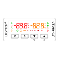
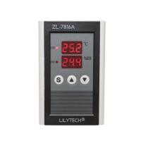
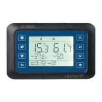
Explains the function and state of various display icons and their corresponding operations.

Key Operation

Temperature and Humidity Setting

Procedure for adjusting temperature and humidity setpoints using controller buttons.

System Parameter Settings

Guide to entering and modifying system parameters using parameter codes.

Parameter Code and Setting Instruction

Detailed table of parameter codes, functions, ranges, and factory settings for the controller.

Control Function Instructions

Temperature Control

Details on cooling and heating control logic based on temperature settings and difference.

Temperature Correction

Method for correcting temperature readings based on sensor placement.

Humidity Control

Instructions for dehumidification and humidification control modes.

Dewing Warning

Explanation of dewing warning triggers and display indicators.

Humidity Correction

Procedure for calibrating humidity sensor readings.

Timed Control

Details on timing functions for load control (R4, R5).

Sensor and Fault Alarm

Information on sensor operation, fault detection (E1), and warning outputs.

Factory Setting

Reference to factory default parameter configurations.

Controller Installation

Installation Procedure

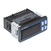
Step-by-step guide for physically installing the controller unit.

Electrical Connection

Electrical Wiring Diagram

Schematic showing terminal connections for sensors and loads.

Related product manuals