
А
АлександрJan 30, 2026
Можно вместо входной нагрузки 220в.переного тока подключить 12в. постоянного тока?
Можно вместо входной нагрузки 220в.переного тока подключить 12в. постоянного тока?
Specifies the power input options for the controller, either 12Vac or 12Vdc.
Details the sensor type, wire length, and accuracy for humidity and temperature measurements.
Defines the adjustable ranges for humidity and temperature, and the output current capacity.
Specifies the environmental conditions and power consumption of the controller.
Explains how the controller display indicates sensor status and output conditions.
Provides instructions on how to enter, navigate, modify, and save settings using the controller buttons.
Describes how temperature control functions based on setpoints for heating and cooling.
Explains humidity control logic for humidifying and de-humidifying based on setpoints.
Details how to calibrate temperature and humidity sensor readings for accuracy.
Lists critical safety precautions for wiring, environment, and device handling.
Provides dimensions and visual aids for installing the controller unit.
Illustrates the sensor and load connections for power and control circuits.
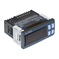
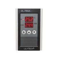
This document describes the ZL-7816A Humidity and Temperature Controller, Version A1.01a.
The ZL-7816A is designed to control both humidity and temperature based on user-defined set points. It features a single humidity and temperature sensor that is connected to the device. The controller provides two independent outputs: one for temperature control and another for humidity control. Each output is capable of handling a load of up to 7A at 250Vac (pure resistance).
The device features two display windows. The upper window typically shows parameter codes during setup, while the bottom window displays the corresponding values. In normal operation, these windows display the current temperature and humidity readings. The controller includes two "out" LEDs. The upper "out" LED illuminates when the temperature output is energized, indicating that the temperature control function is active. Similarly, the bottom "out" LED lights up when the humidity output is energized, signifying active humidity control. In cases where the sensor is not properly connected or has failed, the display will show "--.-" to indicate an error.
To enter the setting status, the user must press and hold the 'S' button for 2 seconds. Once in setting status, the upper display window will show the parameter code, and the bottom window will show its current value. The 'S' button is used to cycle through the available parameter codes in the following sequence: S01 -> S02 -> SC1 -> S03 -> S04 -> SC2. To adjust the value of a selected parameter, the user can press the '▲' (up) or '▼' (down) buttons. Holding these buttons down will enable a fast-set mode for quicker adjustments. To save the settings and exit the setting status, the 'S' button must be pressed and held for 2 seconds again. If no key operation is detected for 30 seconds, the device will automatically exit the setting status, and the settings will be saved.
The temperature control function operates based on the values set for S01 (temperature output energized set point) and S02 (temperature output de-energized set point). If S01 is equal to S02, the temperature control function will be inactive. If S01 is less than S02, the device operates in heating mode:
The humidity control function operates based on the values set for S03 (humidity output energized set point) and S04 (humidity output de-energized set point). If S03 is equal to S04, the humidity control function will be inactive. If S03 is less than S04, the device operates in humidifying mode:
The device allows for calibration of both temperature and humidity readings to ensure accuracy. The tolerance of the measured room temperature can be adjusted using the SC1 parameter. The tolerance of the measured room humidity can be adjusted using the SC2 parameter. It is crucial to note that the sensor should not be plugged in or unplugged, nor should other wires be connected, while power is supplied to the device.
The device requires a 12Vac or 12Vdc power supply. It is designed to be installed with a single humidity and temperature sensor, which comes with a 1.5-meter wire. For stable operation, the total wire length for the sensor should not exceed 50 meters. The electrical wiring diagram illustrates the connections for the power supply (12VAC/DC), the T/H Sensor, and the humidity and temperature loads. The loads are typically connected to an AC220V supply. The humidity load connects to the 'NO' (Normally Open) and 'COM' (Common) terminals of the humidity output. The temperature load connects to the 'NO' (Normally Open) and 'COM' (Common) terminals of the temperature output. The 'NC' (Normally Closed) terminals are also available but not used in the standard configuration for energizing the loads.
Several warnings are provided to ensure safe and correct operation:
| Resolution (Temperature) | 0.1°C |
|---|---|
| Resolution (Humidity) | 0.1%RH |
| Protection level | IP20 |
| Output signal | Relay output |
| Output load | 10A/250VAC |
| Setting range (Temperature) | -40°C - 99°C |
| Accuracy (Humidity) | ±3% RH |