WTR Series
Installation Instructions
L120 Installation & Maintenance Manual 120-11000 A
Setting Procedure
1. Open the Compartment Cover (piece #200 of Figure 9).
2. Put the actuator into manual operation. Use the handwheel to operate the valve in the
“open” direction. While operating the valve, note the direction of the Intermediate Shaft
(B) corresponding to the rotor or rotors to be set.
3. When the valve is fully open, close it one turn of the handwheel to allow for coast of
moving parts.
4. Push in the Setting Rod (A) and turn one-quarter turn. The rod will latch in this
depressed position.
5. Refer to the applicable wiring diagram for contact development. The limit switch contact
is closed when the rotor is engaged with the plunger. If the rotor to be set has not turned
90 degrees to operate the plunger, turn the intermediate shaft in the same direction as
noted in Step No. 2 until the rotor clearly trips the switches. This rotor is now set
correctly.
6. Before moving the valve, depress and turn the Setting Rod (A) one-quarter turn to the
spring released position. Insert a screwdriver into the intermediate shafts to ensure that
they will not move.
CAUTION: Do not operate the valve when Setting Rod (A) is in a fully depressed
position. Loss of contact setting will occur and the setting rod will be damaged.
7. Operate the valve by handwheel to fully “close” position; reverse direction by one turn of
the handwheel to allow for coast of moving parts.
8. Set the other rotors by following Steps No. 4 through 6.
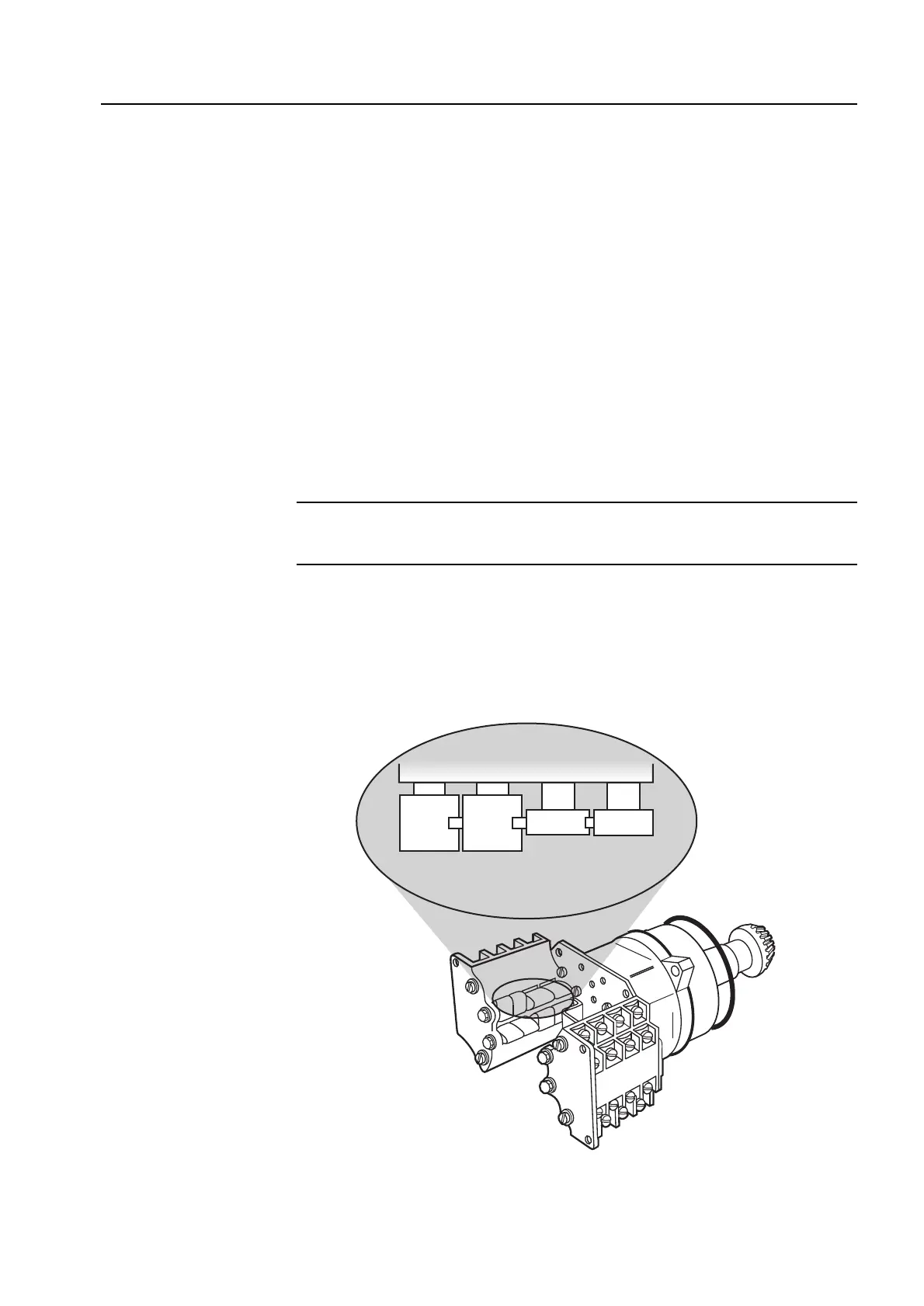
Figure 4 – Setting the open and closed contacts
8