Page 75 of 295
Feedback specifications
Dual Hall, Encoded (F3) is used only for LINAK A/S control boxes.
Dual Hall, digital (F2) is used for not LINAK A/S control boxes.
Dual Hall, digital (F2) positioning.
Item Specification Comment
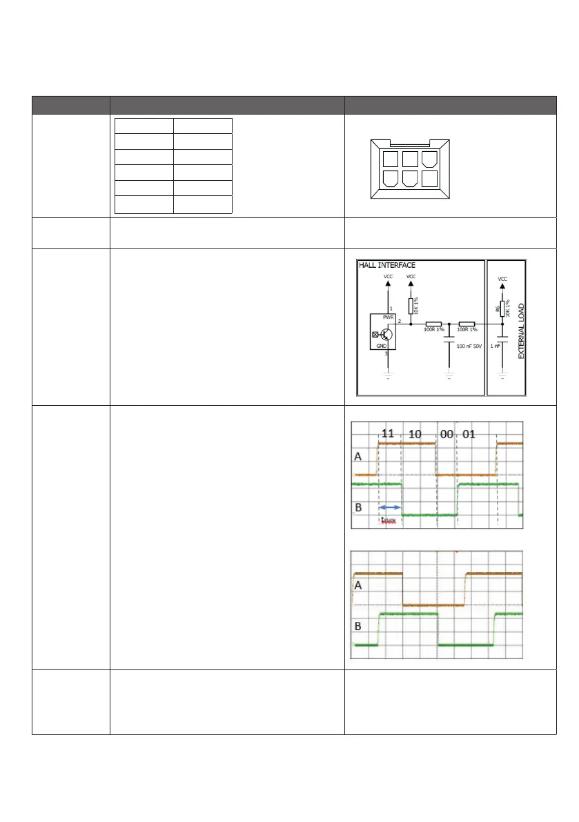
Pin
configuration
Pin 1 GND
Pin 2 VCC
Pin 3 M+
Pin 4 HALL A
Pin 5 HALL B
Pin 6 M-
Connector in LA40 housing:
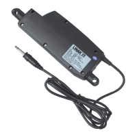
VCC 4 - 15V
Feedback circuit has to be powered 50 ms before driving,
and until actuator has stopped moving
Current Maximum 15 mA @10kΩ and 1nF load.
See diagram.
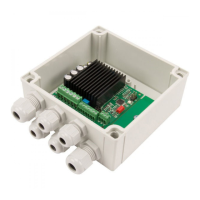
HALL A/B TState is minimum 5ms in all states (11,10,00,01)
Duty cycle Hall A 30 - 70%
Duty cycle Hall B 30 - 70%
Low level < GND + 0.5V @10kΩ and 1nF load
High level > VCC - 0.5V @10kΩ and 1nF load
Driving out, the Hall B signal will go high when Hall A signal
is low.
Driving in, the Hall A signal will go high when Hall B signal is
low.
Driving out:
Driving in:
Resolution The feedback system gives 16 state shifts per spindle turn.
3 mm pitch => 0.1875 mm per shift
4 mm pitch => 0.25 mm per shift
On 100 mm stroke you will have the following number
of pulses:
3 mm pitch => 533 shifts
4 mm pitch => 400 shifts