Do you have a question about the Lincoln Electric NA-3 and is the answer not in the manual?
Important safety warning regarding proper installation and operation.
Precautions to prevent electrocution during welding operations.
Protection against eye and skin damage from welding arcs.
Risks associated with welding fumes and gases and necessary precautions.
Preventing fires and explosions caused by welding sparks.
Safe handling and storage of gas cylinders to prevent explosions.
Safety measures for equipment powered by electricity.
Safety precautions for equipment powered by an engine.
Specifies the necessary electrical input power for the equipment.
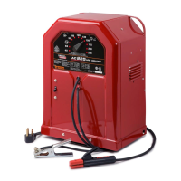
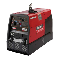
Details the types of welding power sources compatible with the system.
Information on wire feed speed ranges and available gear ratios.
Provides the physical size and weight specifications for the control boxes.
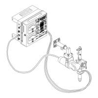
Overview of requirements for installing the control box and welding head.
Steps for mounting the control box on a carriage or fixture.
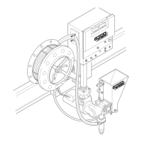
Guidelines for mounting the welding head, ensuring proper alignment and insulation.
Details the voltage and power needed for the wire feed motor and controls.
Instructions on connecting the control box to the welding head via cables.
Guidance on connecting the control box to various welding power sources.
Essential safety guidelines to follow before and during operation.
Simple steps for making production welds without control readjustment.
Explanation of the controls on the NA-3N, NA-3S, and NA-4 units.
Details the controls and components located on the inner panel of the unit.
Instructions for using the optional electronic voltmeter for precise voltage monitoring.
Configuration steps for using Constant Voltage (CV) or Constant Current (CC) power sources.
Procedure for setting up and performing welds using DC Constant Voltage.
Methods and controls for initiating and concluding the welding process.
Overview of standard 'hot start' and 'cold start' arc striking methods.
Detailed steps for initiating welding with a 'hot start' sequence.
Steps for initiating welding with a 'cold start' sequence, recommended for precise starting.
Using PC board for controlled penetration and bead shape at weld start.
Configuring travel start and stop sequences for various welding applications.
Adjusting sequence to prevent electrode sticking and control burnback.
Introduction to the accessories available for the NA-3 and NA-4 welding systems.
A comprehensive list of available accessories with brief descriptions.
Procedures for inspecting and maintaining the control box, including circuit protection.
Maintenance tasks for the welding head, including drive gear box and motor.
Instructions for replacing motor pinion and first reduction gear to alter wire feed ratios.
Guidance on maintaining drive rolls, guide tubes, and gear ratios for wire drive.
Inspection and maintenance of slide bushings and guides for wire straighteners.
Maintenance of contact tips and assemblies to ensure good electrical contact.
Lubrication of reel shaft and brake assembly for wire reels.
Periodic oiling of carriage components for smooth operation.
Lubrication and greasing of the vertical lift adjuster housing and components.
Greasing of sliding surfaces and gear cavity for horizontal adjuster.
Overview of the NA-3 and NA-4 automatic wire feed control units.
Explanation of how 115 VAC power is supplied and regulated within the control box.
Description of the SCR-controlled power supplies and logic board functions.
How the variable voltage board controls wire feed speed and senses arc length.
Function of optional boards for controlling initial weld parameters and crater fill.
Basic understanding of Silicon-Controlled Rectifier (SCR) circuitry used for wire speed control.
Step-by-step process for diagnosing and locating machine malfunctions.
Guidelines for identifying and resolving issues related to PC board failures.
Systematic approach to identifying and resolving common operational problems.
Diagnosing and resolving issues related to wire feed, circuit breaker, start/stop, and control problems.
Troubleshooting common issues with the automatic travel system.
Diagnosing and resolving problems with the flux or water solenoid valve operation.
Schematic showing the electrical connections for the NA-3 system.
Schematic showing the electrical connections for the NA-4 system.
Diagram illustrating the operational flow of the NA-3 system.
Diagram illustrating the operational flow of the NA-4 system.
Schematic for the logic PC board.
Schematic for the variable voltage PC board.
Schematic for the control PC board.
Schematic for the optional start PC board.
Schematic for the optional crater fill PC board.
| Brand | Lincoln Electric |
|---|---|
| Model | NA-3 |
| Category | Welding System |
| Language | English |