Do you have a question about the Lincoln Electric VANTAGE 400 and is the answer not in the manual?
Warnings and precautions to prevent electric shock while welding.
Precautions for engine-powered equipment operation, including ventilation and fuel handling.
Dangers of breathing welding fumes and gases, ventilation requirements.
Safety for installing and operating electrical equipment.
General safety warnings and precautions before performing maintenance.
Instructions on navigating and using the troubleshooting section.
Steps for troubleshooting and replacing PC boards safely.
Troubleshooting steps for major mechanical or electrical damage.
Diagnosing no output in any mode with normal engine and auxiliary output.
Diagnosing a cold welding arc with normal engine and auxiliary power.
Diagnosing issues with maintaining a steady welding output.
Diagnosing unsteady output related to engine or control issues.
Diagnosing when front panel output control is inactive with remote connected.
Troubleshooting when the machine is locked in CC-Stick mode.
Diagnosing blank, incorrect, or partial front panel display readings.
Diagnosing why the engine won't crank when the start button is pressed.
Diagnosing why the battery does not stay charged.
Diagnosing why the engine shuts down after start button release.
Diagnosing engine shutdown and breaker trip.
Diagnosing lack of full engine power.
Continued troubleshooting for engine not idling down.
Diagnosing no high idle when striking arc or applying load.
Continued diagnosis of no high idle on arc strike.
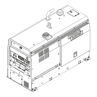
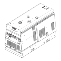
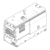
Procedure for removing and replacing the machine's case covers.
Continued procedure for removing and replacing case covers.
Steps for reassembling components after service.
Procedure to safely discharge capacitors in the chopper module.
Continued procedure for discharging chopper module capacitors.
Test to determine if the shutdown solenoid functions correctly.
Continued test for the fuel shutdown solenoid.
Test to determine and adjust engine operating speed (RPM).
Continued test for engine throttle adjustment using frequency counter.
Procedure for adjusting engine high and low idle speeds.
Test to determine idler solenoid function and resistance values.
Continued test for the idler solenoid.
Test to determine if the engine alternator is properly charging the battery.
Continued test for the engine alternator charging system.
Guidance for testing and maintaining the brush and slip ring system.
Continued service procedure for brushes and slip rings.
Test to determine if the rotor winding is open, shorted, or grounded.
Continued static test for rotor resistance and ground.
Test for rotor winding faults under normal operating stress.
Test to determine if the rectifier is grounded or has failed diode groups.
Test to determine if the chopper module is functioning properly.
Test to help determine if the chopper module is shorted.
Test to determine if the weld control PC board produces PWM gate signals.
Test to determine if the weld control board receives accurate feedback.
Test for output control, arc control, mode switch, and wiring.
Test for problems with remote receptacle wiring and weld terminal switch.
Steps for diagnosing no welding or auxiliary output with normal engine.
Diagnosing poor arc quality with excessive spatter.
Troubleshooting when a feeder does not function via 14-pin amphenol.
Troubleshooting wire feeder connection to weld output.
Troubleshooting engine cranking but not starting.
Troubleshooting engine shutdown shortly after starting.
Troubleshooting engine not idling down to low RPM.
Troubleshooting engine not staying at low idle.
Continued troubleshooting for engine not staying at low idle.
| Fuel Type | Diesel |
|---|---|
| Auxiliary Power (kW) | 10 |
| Rated Output | 400A at 100% Duty Cycle |
| Frequency (Hz) | 60 |
| Welding Processes | Stick, TIG, MIG |
| Rated RPM | 1800 |
| Output Range (Amps) | 10-400 Amps |
| Engine Model | Kubota V3300-CR-TE4 |
| Fuel Tank Capacity (gallons) | 25 gallons |