Do you have a question about the Lincoln Electric NA-5N and is the answer not in the manual?
State-specific warnings regarding engine exhaust.
Safety precautions specific to engine-powered equipment.
Hazards and precautions related to EMF exposure during welding.
Precautions to prevent electrocution hazards.
Protection measures against arc ray burns.
Safety guidelines for avoiding hazards from welding fumes and gases.
Precautions to prevent fire and explosion risks from welding sparks.
Safety measures for handling compressed gas cylinders.
Details on electrical input, wire feed speed, and physical dimensions.
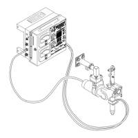
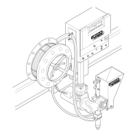
Instructions for mounting the control box and welding head.
Information on proper wiring procedures and connections.
How to set or change electrode polarity for the NA-5 control circuit.
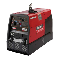
Diagrams showing how to connect the NA-5 to various power sources.
General safety guidelines to follow during operation.
Step-by-step guide for making production welds.
Explanation of the NA-5 control panel layout and functions.
Steps to configure the NA-5 welding system before welding.
Procedures for initiating and concluding the welding cycle.
Introduction to the section listing available accessories.
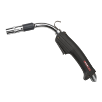
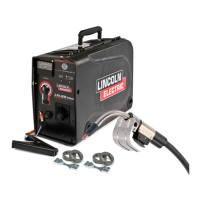
Detailed list and descriptions of accessories for the NA-5 system.
General inspection and circuit protection for the control box.
Maintenance for the wire drive gear box and motor.
Maintenance for drive rolls and wire straighteners.
Maintenance procedures for various optional accessories.
Overview of the NA-5 as an automatic wire feed control unit.
How the NA-5 unit receives and processes input power.
Explanation of how AC voltages are processed and supplied to various boards.
How these boards interpret signals and control motor operation.
Explanation of how silicon controlled rectifiers function in the system.
Step-by-step instructions for diagnosing and fixing machine malfunctions.
Guidelines for identifying and replacing faulty PC boards.
Common issues related to wire feeding and their solutions.
Troubleshooting specific issues with different operating modes.
General functional issues not specific to modes or wire feeding.
Diagnosing problems with the travel mechanism.
Comprehensive diagram showing all electrical connections and components.
Schematic detailing the logic PC board circuitry.
Schematic detailing the power PC board circuitry.
Schematic detailing the voltage PC board circuitry.
Schematic detailing the control circuit of the NA-5.
Schematic detailing the procedure board circuitry.
Schematic and layout for the meter PC board.
| Brand | Lincoln Electric |
|---|---|
| Model | NA-5N |
| Category | Welding System |
| Language | English |